...Return To Mine & Other Bonneville Car Construction Pages
.Previous Page...............B'ville Car Index Page.........................Next Page
.......................................-- Body Mounts Part I --.................
.................. .
.
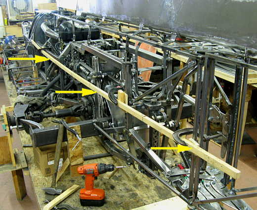
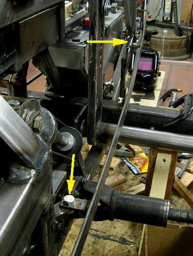
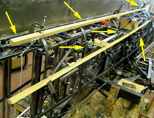
On this page we will make some body mounts that hopefully the aluminum body will fit and be attached to. I started with this piece of wood (arrows) that I bent in the desired shape and clamped to the frame at various points. I've tried to keep the angle that the body curves in at at less than 7 degrees in the back. Seems like I've read that the air will follow and be less attached at that angle, although if for sure won't be attached to the body skin back here like it will be on the very front of the car.
.................. .
.
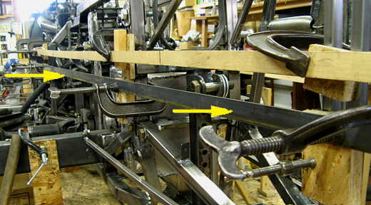
Next I placed this .120 thick by 1 inch wide strap down the car horizontal to the ground and directly in line with the inside edge of the wood above it. At this point it is also clamped to the car. It is down a little less than 24 inches from where the body will meet the air intake/exhaust/tail.
.................. .
.
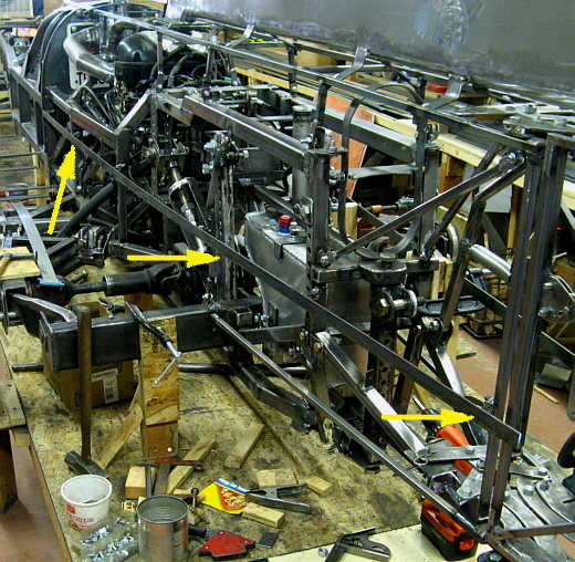
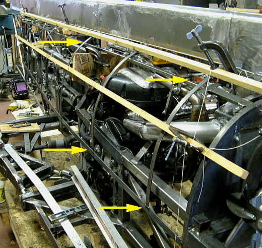
I then would take the upright (arrows) and slide it up against the build table on the other side of the car and measure in from it to the metal that we placed in the last picture. Next I'd come to this side of the car and place the inside edge of that piece of wood the same distance from the edge of the build table. I'm making both sides of the car the same this way using the edges of the build table as a reference. The car frame is centered on the build table.
.................. .
.
Like the other side I placed a strap down this side (arrows) under the wood above and then removed the wood. Next using the upright I double checked that the straps on both sides of the car where the same distance in at the same location on the car.
................................... .
.
With that done tabs were welded to the frame and the strap along it's length. The arrows show two of these.
.................. .
.
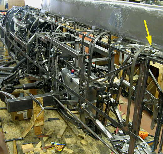
Another view of the strap bolted to the frame at this point. The same was done for the other side of the car.
.................. .
.
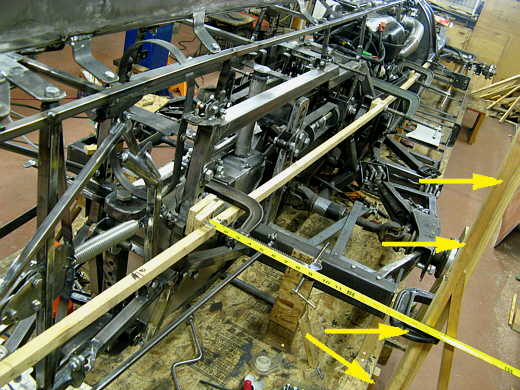
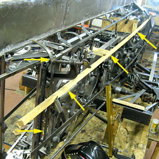
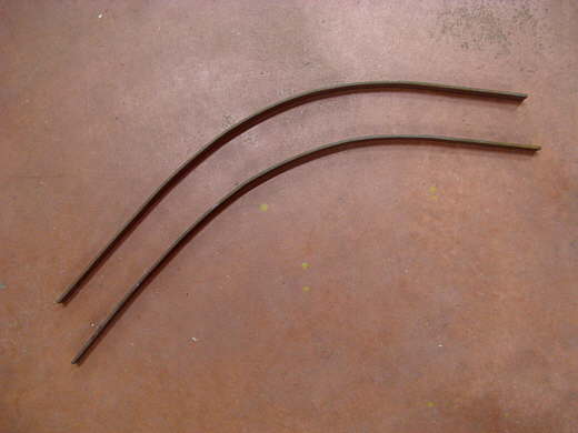
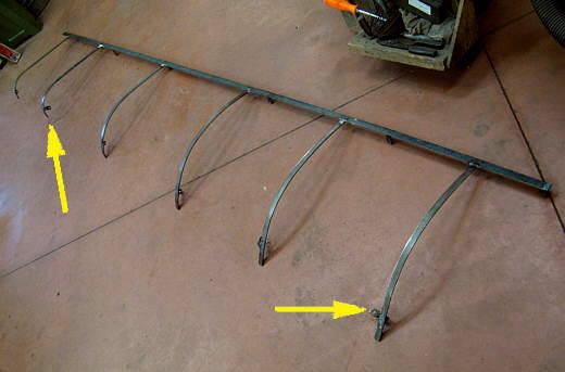
Up front we are using the firewall perimeter as the outside shape of the body. In the rear I bent a strap (two left arrows) that was how I wanted the body to be shaped at the rear. This is right in front of the chute doors. They will be done later to blend in with this. Notice how back here the rib (two left arrows) just curves at the top and is flatter going down to the previously installed strap. A flat tail will help more to establish the center of pressure towards this end of the car than a round sided tail would. The other arrows point to another piece of wood that goes from the back rib up to the firewall and is braced out at a couple places (two right arrows). It will help me make the rest of the ribs.
.................. .
.
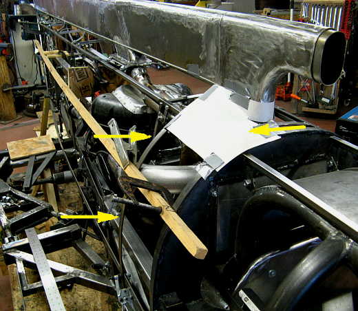
I made another rib not too far back from the firewall (two left arrows). The top right arrow points to some cardboard I was playing with to help me visualize what I would do with the body in this area. It won't be like the cardboard.
.................. .
.
Each time I bent a rib for the right side of the car I used it for a pattern and bent one for the left side of the car that would go in the same location on that side. I bent these by opening the vise jaws to different distances and just worked the piece by bending just a touch and then moving it ahead just a tad and bend a tad more. It worked best to over bend them and then to just start straighening them out to where I wanted them. I was using my knee, but the vise worked better since I could make lots of small bends closer together. If I kinked it I would just take the hammer to it and re-do that area.
.................. .
.
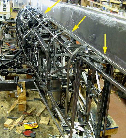
I also added the top board to help determine the shape on the sharper bend at the top of the ribs and ran a string line down the side (3 top arrows). The ribs were bent so they hit the strap at the bottom and the insides of the two pieces of wood and then just went to the string line. As each one was bent on this side as I mentioned before I used it as a pattern for the other side of the car.
.................. .
.
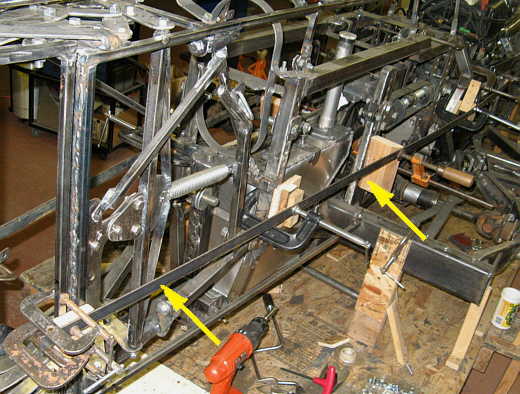
The ribs started long at the bottom and once they fit inside the wood and to the string line I marked them where they hit the top of the strap at the bottom (bottom two arrows) and then cut them there and then tacked them to the strap. Once they were secure at the bottom I welded tabs to their tops and to that small frame rail up there (top two arrows) Once I had one bolted up there I move on to the next one.
.................. .
.
The arrow here points to one of the more visible tabs where the rib is bolted to the frame. The ribs are spaced at about 23 1/2 inches apart. I hope to work with 48 inch wide pieces of aluminum at a time and I'm hoping this spacing will work out so that I can trim the aluminum at the intersection where body pieces will meet.
.................. .
.
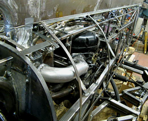
Next the strap an ribs were removed and everything was finish welded as I couldn't get to it all on the car. Then the outsides of the joints where the aluminum will sit against were ground smooth.
.................. .
.
I put the strap and ribs back on the car and welded in these top pieces to tie it altogether and hopefully the body will seat against them also.
.................. .
.
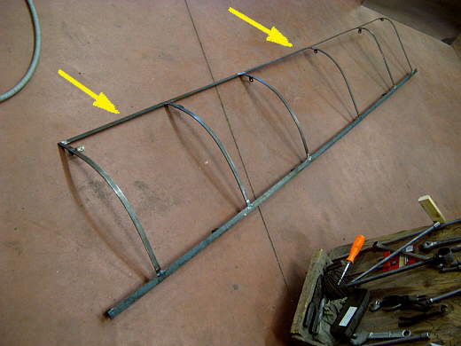
Once again a string line was established (arrows) and the top of the ribs and connector pieces were tweaked into alignment with the string line. Here from the back of the car you can start to visualize the upper body shape.
.................. .
.
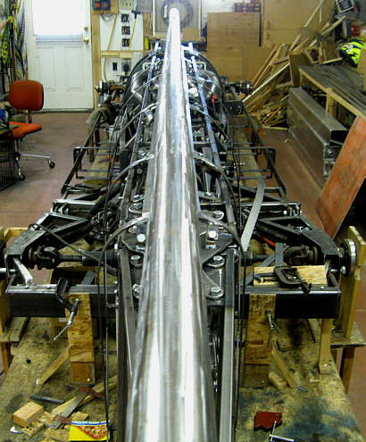
And here we are look towards the rear and the flatter sides back there and.............
................................ .
.
............. here is an overhead shot. Boy I hope I can make the aluminum fit this. If not then I guess it will be onto fiberglass as a second option.
..............................................................Next
Page