...Return To Mine & Other Bonneville Car Construction Pages
.Previous Page...............B'ville Car Index Page.........................Next Page
.......................................-- Finish Intake Track --.................
.................. .
.
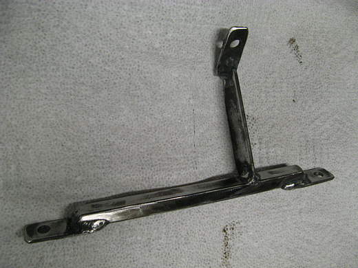
On this page we will connect the plenum under the inlet scoop to the air box on the motor. First this bracket was made to hold the front of the air box securely.
.................. .
.
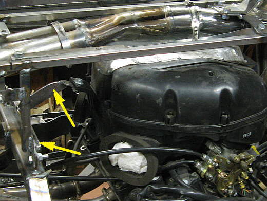
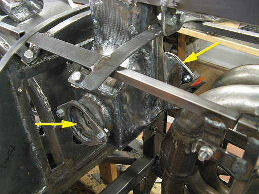
The one part attaches to the front of the air box (top arrow) and the cross piece attaches to the frame.
.................. .
.
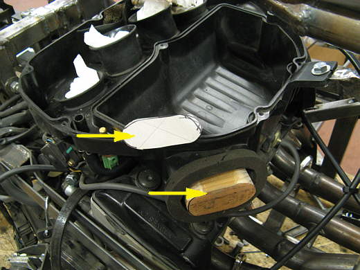
The air box has two inlets on both sides of the front (bottom arrow). I made a cardboard pattern of the opening (top arrow) and then cut a piece of wood to that shape (bottom arrow).
.................. .
.
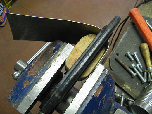
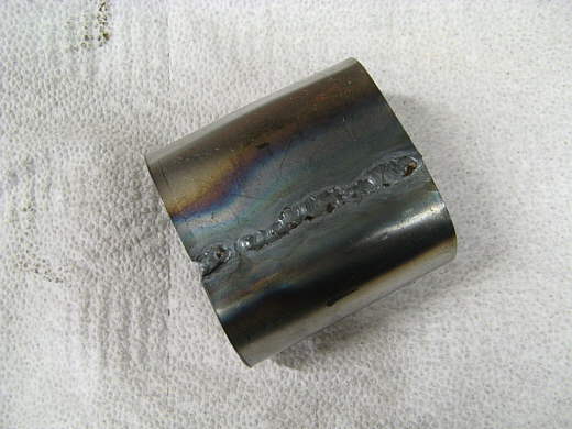
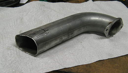
Using the vise and a c-clamp some 20 gauge was wrapped around the plug and ............
.................. .
.
Then cut to length and welded with the tig. Not too pretty, but this 20 gauge is pretty thin.
.................. .
.
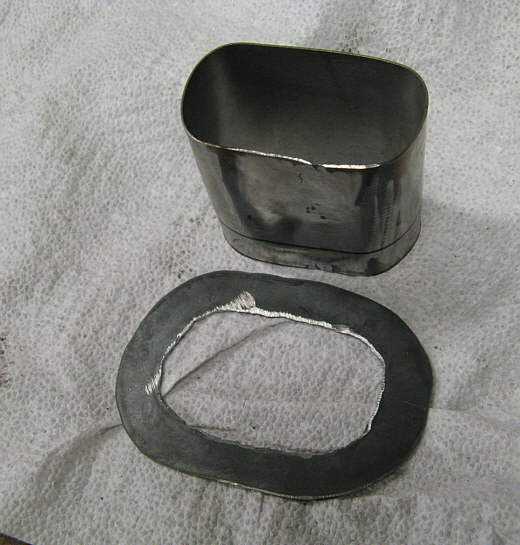
Then a piece was cut for a flange and ..................
.................. .
.
............ these were welded to the first pieces.
.................. .
.
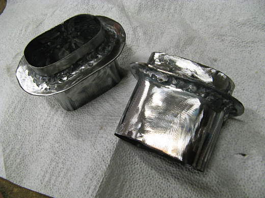
They seemed to fit very well, so I proceeded...............
.................. .
.
............. by attaching the two flanges I had made a few pages back to both sides of the plenum outlets and I took some ......
.................. .
.
.............. 2 1/2 inch exhaust tubing I had left over from my truck and tacked one end to the flange and squared the other end up with a hammer on an anvil.
.................. .
.
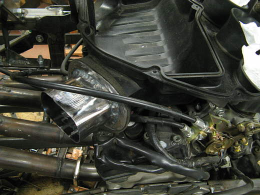
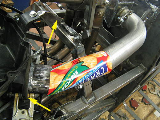
With the tubing on one side and the inlet on the other I made a quick cardboard pattern of the area I need to connect and then cut some 20 gauge to that size and clamped it in place and started to weld and bend it. The clamp on the right (right arrow) is clamping the inlet piece tight against that foam rubber and inside the inlet of the air box for a tight fit there.
.................. .
.
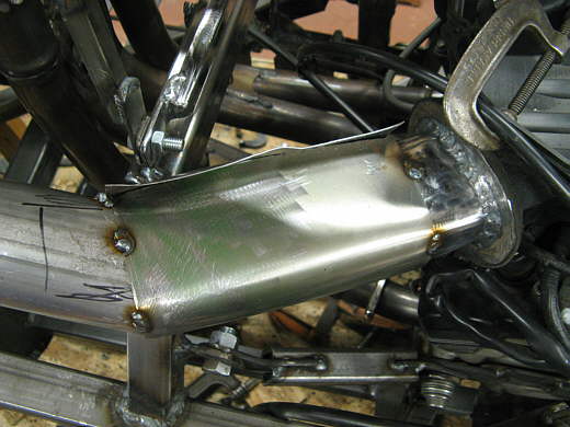
I continued to wrap the piece around the two ends tacking as I went.
.................. .
.
Here it is read to be finished welded with the tig.
.................. .
.
I did the same with the other side, clamping the inlet piece tight against the air box (bottom left arrow) and since the angles were different than the other side I had to make a new pattern. The top arrow points to the bracket that was made at the top of this page to hold the front of the air box.
.................. .
.
Here is the pattern and ..................
.................. .
.
............. here is the metal cut from the pattern and wrapped around the two ends ready for final welding. The wrapping was done in place on the motor.
.................. .
.
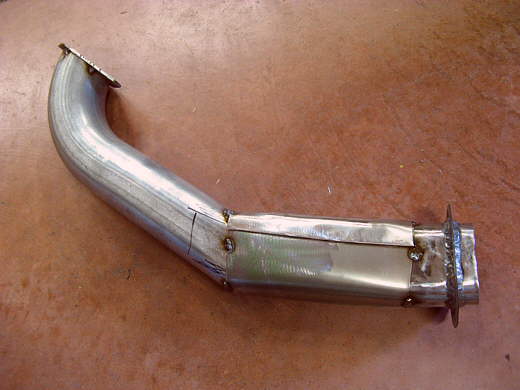
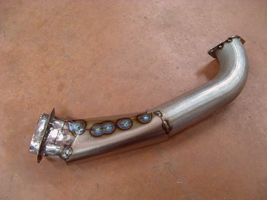
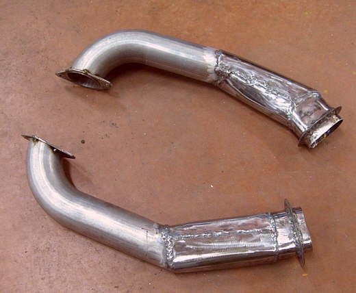
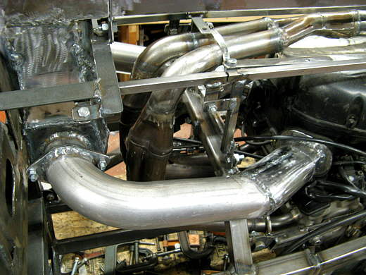
Here are the two pieces finished except for finish welding on the flanges which .....
.................. .
.
.............. was done next and shown here.
.................. .
.
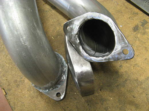
The left side finished and in place. I'll make some paper gaskets for the flanges.
.................. .
.
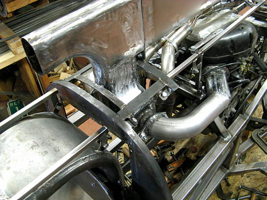
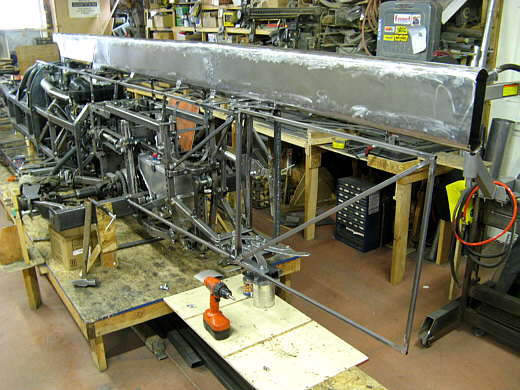
This view shows ho the air enters the scoop and goes to the plenum under it and then back to the air box. I tried to keep the volume constantly increasing on the way to the air box. Nothing that was designed with real numbers, but just kind of what I think should happen according to some folks.
.................. .
.
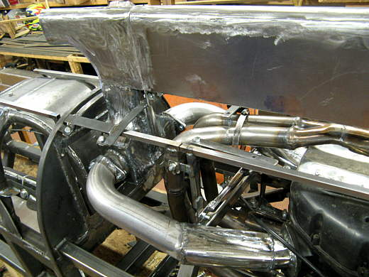
When we move to a turbo motor the air will go from the plenum to the turbo, then to the motor.
.................. .
.
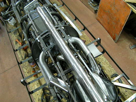
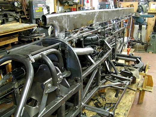
One last view from the top looking down. I like the way all of these pipes look. Pretty cool.
.................. .
.
And two final shots of the air inlet/exhaust/tail.
.................. .
.
This has been a lot of work over the last couple weeks to make this, but I'm happy with it at this point and except for paint it is done!!
..............................................................Next
Page