...Return To Mine & Other Bonneville Car Construction Pages
.Previous Page...............B'ville Car Index Page.........................Next Page
..............................-- Intake/Exhaust/Tail Part V --.................
.................. .
.
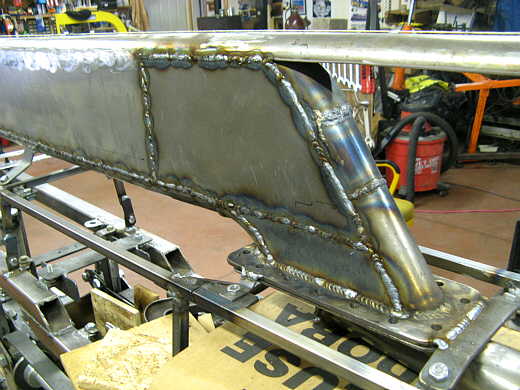
Let's finish the exhaust track. I held up another piece of sheeting and marked it where in needed to be cut to weld to the exhaust tube coming up from the front of the flange. Then while I still could I did the same for the other side. I couldn't just weld a piece down the side for two reason. One I could have welded this one to the pipe from this side, but then couldn't have gotten in to weld the one on this side the same way. The second reason is I wanted a removable section behind the scoop area back to the beginning of the exhaust so that I could remove any of the three section independent of each other.
................. .
.
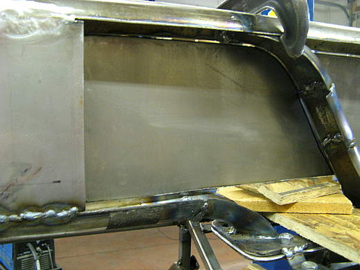
Here I'm using a string line to line up this panel I'm welding in so that the sides of the the whole air intake/exhaust/tail stay flat on the sides and don't bulge in and out at the weld seams.
................. .
.
This side is welded up, but there still remains a small area at the bottom that has to be filled in.
................. .
.
Here that area is finished on the other side.
................. .
.
Just another view...
................. .
.
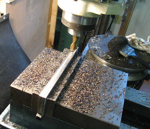
Some uprights had to be made to fit inside of the removable section just forward of the exhaust section. Since I used 2 inch wide tubing and I'm covering this part with 16 gauge (roughly 1/16th of an inch thick) I had to mill these 2 inch wide pieces of strap down to 1 7/8ths inch wide to get a 2 inch outside width with the sides on.
................. .
.
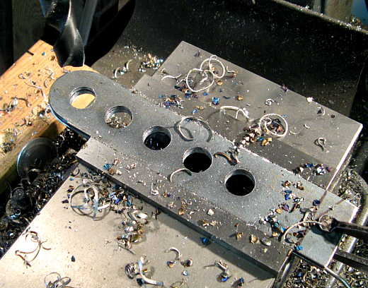
Two of those pieces I cut lightening holes not to lighten the car much, but just because they look cool. Not show here is two holes that were drilled in at the bottom (right side) to clamp these pieces together. The rounded top is to fit the inside of the tubing.
................. .
.
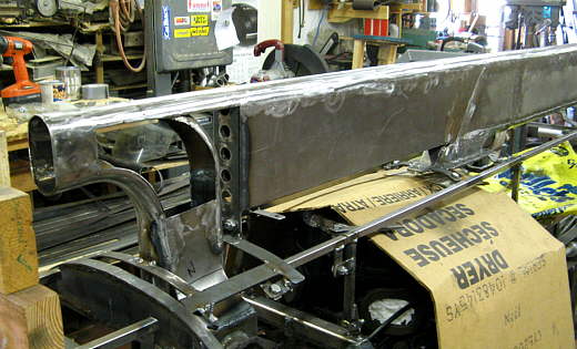
Here the front two are bolted together and I welded one to what will be the scoop area to the left and the other was welded to what will become the removable section to the right. Again I had to keep these aligned so that the sides would end up straight.
................. .
.
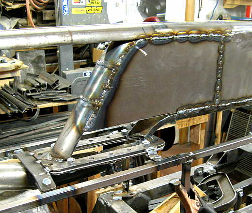
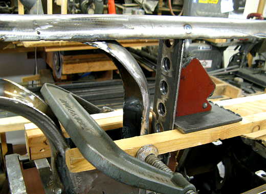
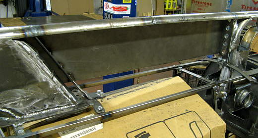
The last one that I had made was welded up at an angle to the tubing at the top and to a bracket (bottom arrow) on the bottom.
................. .
.
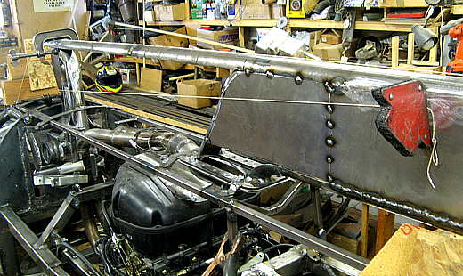
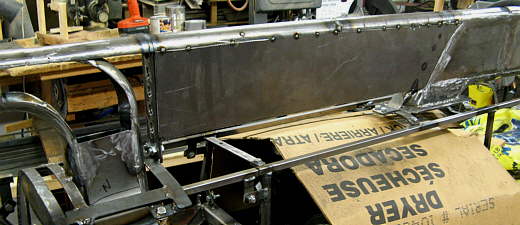
Some more 6 inch high 16 gauge was tacked to the front and rear uprights and to the tubing on the top. This will become the removable section. Actually all three sections can be removed, but this one is to get easier access to the top of the motor.
................. .
.
A view at this point from the other side.
................. .
.
Welded up and pretty much ground down.
.................................. .
.
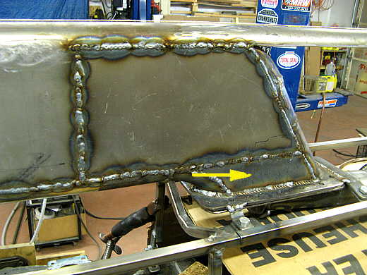
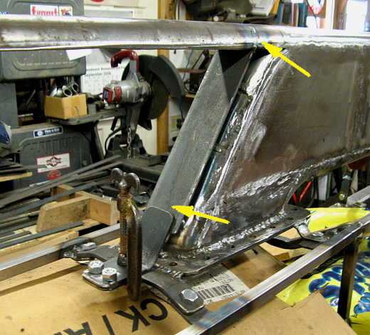
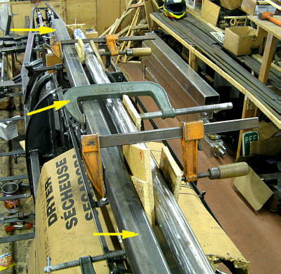
I did end up with some slight distortion side to side on the top. I clamped a piece of square tubing (top and bottom arrows) out a ways on the left side (in this instance) and used a clamp (center arrow) to pull the top of the tubing to the left some. I got things close this way, but there is still maybe 1/16 + or - going down the top assembly. About as good as it is going to get.
..............................................................Next
Page