...Return To Mine & Other Bonneville Car Construction Pages
.Previous Page...............B'ville Car Index Page.........................Next Page
.............................-- Intake/Exhaust/Tail Part III --.................
.................. .
.
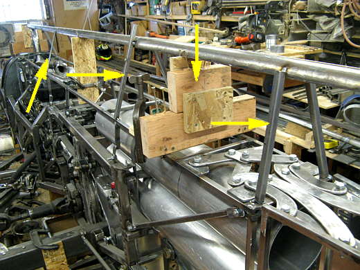
At this point I had to position this whole intake/exhaust/tail as close to the center of the car and at the right height as possible. I found the center line at the front and back of the car and ran a string line between them and for the rest of this part of the build I tried to keep things centered on that line. The arrow pointing straight down points to the blocking that has everything set to the right height. Next temporary angled pieces of scrap were welded in (3 other arrows) to hold the top tubing in place and to not be in the way during the rest of this part of the build.
.................. .
.
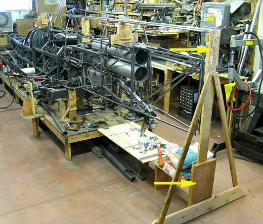
The arrows point to the upright that is centered on the car at the back and.....
.................. .
.
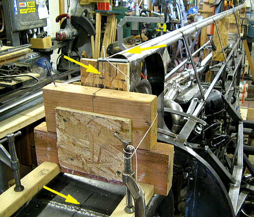
............. this blocking is centered (arrows) up at the front of the assembly and on top of the roll cage. You can see the string that runs from here to the back of the car. The wide angle on the camera makes it look like it is longer that the 12 feet that it is. I figured how large of a cross section (square inches of exhaust area) that I wanted for later with hopefully a 500-600 HP 'busa motor and that determined how high this would be. From the top to the bottom in the rear half will be the exhaust track.
.................. .
.
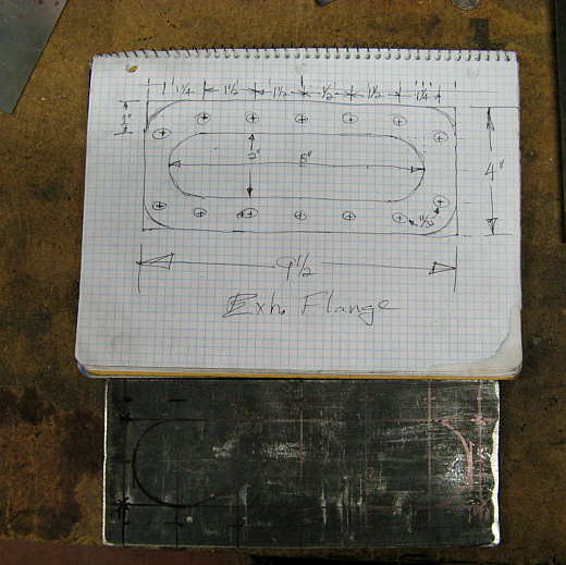
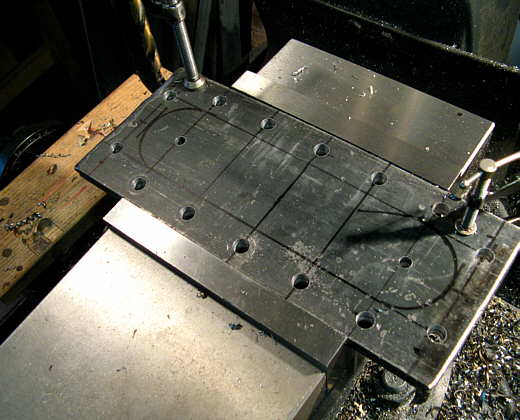
Next I had to make a flange area where the exhaust from the headers would connect to this exhaust track on top of the car. I drew up a plan for a flange and then took two pieces of strap and marked off what I wanted on the strap.
.................. .
.
Actually the markings on the steel are just close as I use the x-y feed on the mill table to get these exact so that I can make gaskets later if I need to and they will fit exactly. That is the nice thing about the accuracy of using a mill and not just drilling holes with a drill press.
.................. .
.
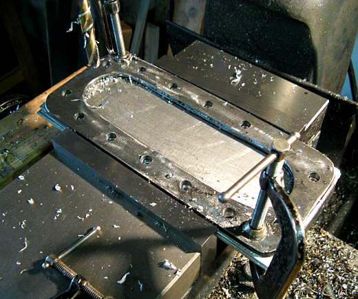
The perimeter holes were drilled and then I shaped the ends of the inside with two hole saw cuts followed by cutting between them with the plasma cutter.
.................. .
.
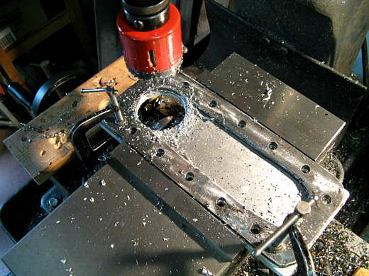
Next two pieces of .090 5052 pretty soft aluminum was put in the mill/drill and drilled with one of the flanges as a template. These ....
.................. .
.
................ pieces of aluminum will be used as gaskets. One now and a spare. Here the hole saw is cutting the ends to shape.
.................. .
.
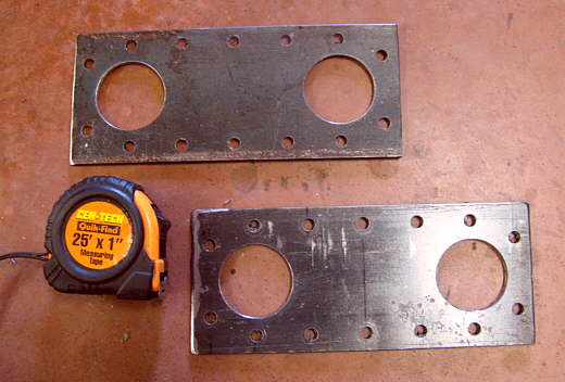
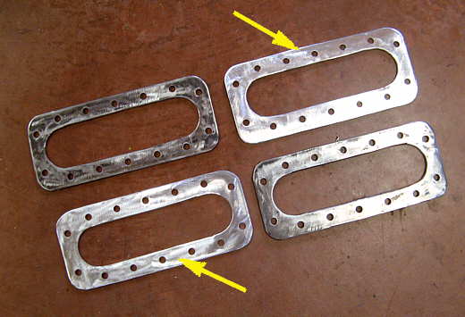
Two finished gaskets (arrows) and the two flanges. One for the header/exhaust pipe and the other for the exhaust track on top of the car.
.................. .
.
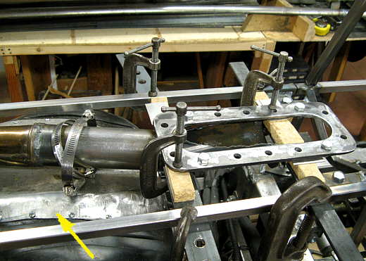
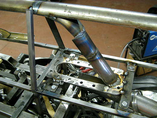
The previously made header/exhaust pipe was cut off at an angle and the two flanges positioned in the center of the car above it.
.................. .
.
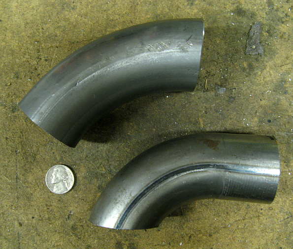
Some more tubing bends that I had where cut in half to use on the exhaust track.
.................. .
.
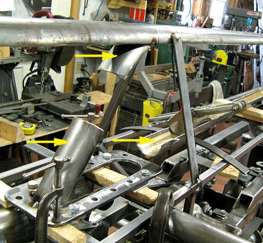
Here the exhaust system is being built from the flange up to the top exhaust tubing at the very top of the car.
.................. .
.
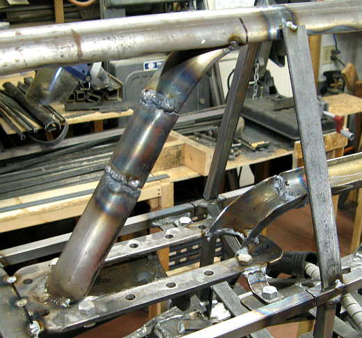
Then a piece was welded in to join the first two. You can see that at this point I had welded mounting tabs to the back sides of the exhaust flange and to the front of it that go to the body mounting framework.
.................. .
.
At the back of the exhaust flange I started the bottom track of the exhaust. The exhaust will end up being 2 inches wide by 8 inches tall with the top and bottom being rounded.
..............................................................Next
Page