...Return To Mine & Other Bonneville Car Construction Pages
.Previous Page...............B'ville Car Index Page.........................Next Page
........-- Conclusion of Throttle/Clutch Linkage --.................
.................. .
.
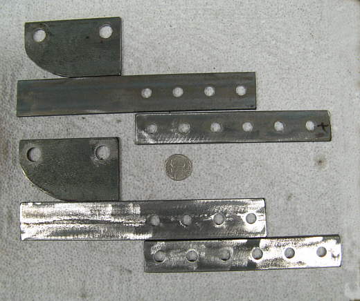
Before I finished the linkage up I want to make an adjustable support for the driver's heel so that it would be easier to operate the two pedals. Other wise your heel would slide on the car floor. These pieces were cut and drilled and ........
.................. .
.
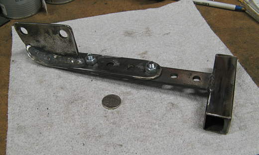
.......... and then welded and bolted together with the addition of the piece of square tubing that your heel rests against.
............................................ .
.
Here it is mounted to the bottom of the pedal assembly with two of the bolts that screw into the bottom spacers. The two bolts on this assembly allow it to be mover fore and aft for the drivers comfort. Now back to the clutch/throttle..............
.................. .
.
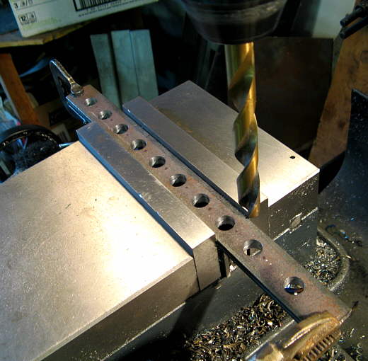
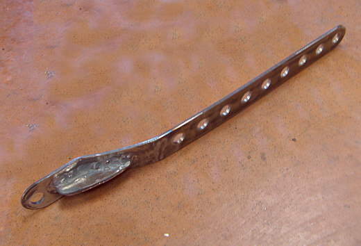
............. linkage. Two pieces of strap were drilled for multiple attach points as if we move the pedal assemblies back and forth the linkage back to the throttle and clutch cables on the engine has to get shorter or longer also.
.................. .
.
The ends were bent for leg clearance to move these pieces away from the pedal and along the frame sides.
.................. .
.
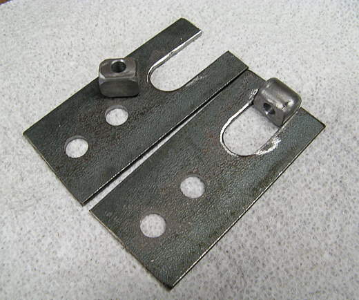
Next was making the pieces that the linkage rods coming from the engine would attach to and these piece in return attach to the last pieces made.
.................. .
.
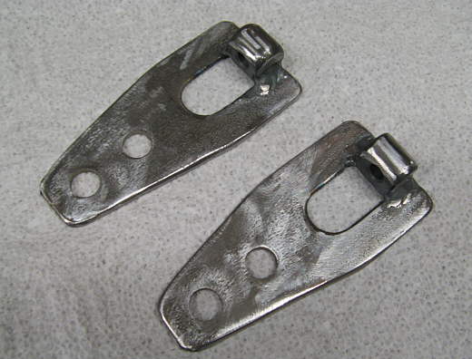
The small pieces made from round stock were welded to the main bracket pieces.
.................. .
.
These pieces are then bolted to the first pieces we made (on the left and in the back) and the rods bolt to them.
.................. .
.
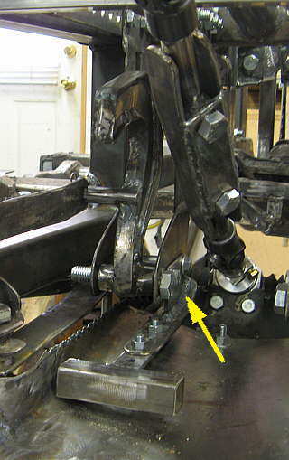
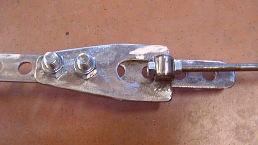
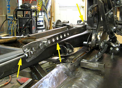
The finished Clutch linkage (almost finished) with the rod coming from the engine (left arrow), the adjustable piece (middle arrow), and the whole works attached to the left side of the clutch pedal. A similar setup was made for the throttle pedal on the other side.
.................. .
.
Another view showing the pedal attach point better.
.................. .
.
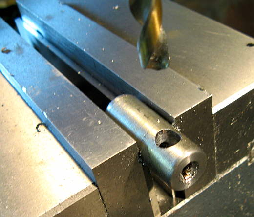
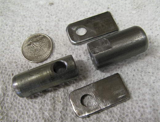
The last thing that I made was a U-Joint for the linkage for the clutch side. The frame angles in at the middle of the cockpit and I wanted to have a U-joint where this occurred. This is 1/2 of the U-joint being made.
.................. .
.
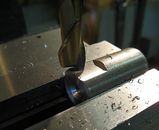
This is the other half of the U-joint.
.................. .
.
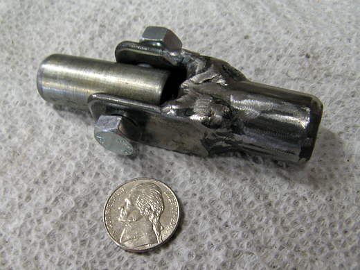
Two tabs finished it up and the tabs were welded to the flats on the right piece to give us ..........
.................. .
.
......... a little miniature U-joint. Both sides were drilled and tapped for the linkage rods.
.................. .
.
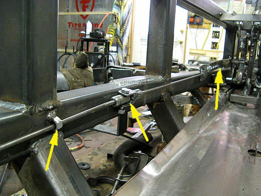
Here the U-joint is in place (middle arrow). The left arrow points to a guide. Since the rod screws into all of the pieces everything can come apart. The right arrow points to the pedal end of the linkage.
.................. .
.
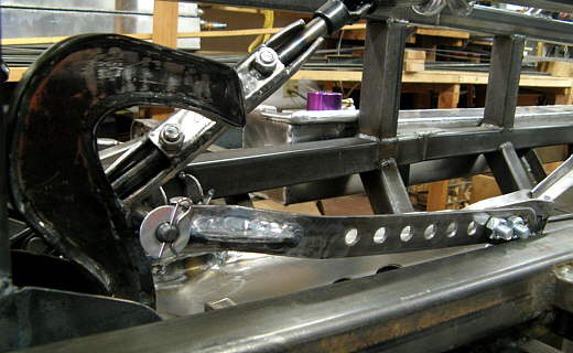
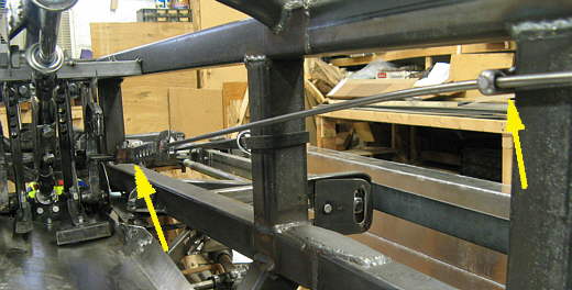
I didn't feel that I needed the U-joint in the throttle linkage as where it was mounted was a more direct line to the pedal assembly. The right arrow points to a guide that holds the linkage rod up above where my arms rest in the sides of the frame area. The left arrow points to where the linkage attaches to the pedal.
I still need to make a toe strap for the throttle pedal to meet the requirements in the rules that you can pull the throttle off with your foot.
..............................................................Next
Page