...Return To Mine & Other Bonneville Car Construction Pages
.Previous Page...............B'ville Car Index Page.........................Next Page
.................................................-- Pedal Brackets --.................
.................. .
.
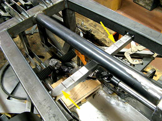
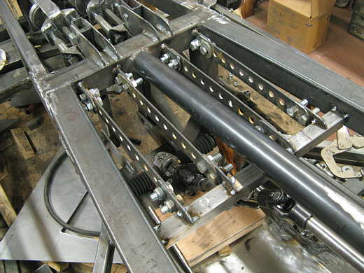
Next up was making brackets for the clutch and gas pedals. The brackets will hang, but the pedals will swing from the bottom of them. I had a hard time coming up with something that would work in the available space yet still give good leverage on the clutch side.
I started by tacking in a cross-member (see two arrows). The brackets will tie into this cross-member and the frame cross-member up ahead of it.
.................. .
.
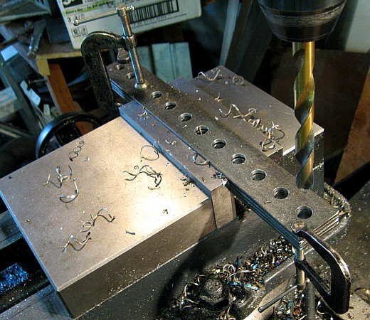
4 pieces of strap were cut and drilled. The holes are so the pedal assemblies can be moved back and ahead to accommodate drivers with different length legs. I've found that with the driver in a reclined (basically laid down) position that placement of the controls is important. If your leg is not in the right position in regards to the pedals it makes it awkward to use them.
.................. .
.
Next pieces were cut that will weld onto the cross-members and the previous made pieces of strap will bolt to.
.................. .
.
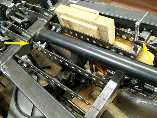
Here the previously made pieces are being tacked into position. One piece would be welded in and then the second assembly would be spaced with the pieces of wood parallel to the first and the end brackets would be welded in (arrows).
.................. .
.
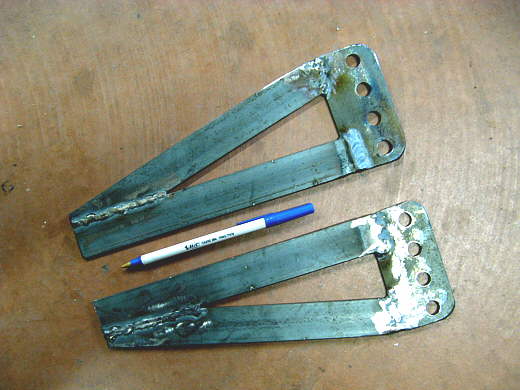
The top pieces are now in place and it is on to building the pieces that will hang from these.
.................. .
.
4 of these pieces were made and they will bolt to the top pieces in any position that is needed.
.................. .
.
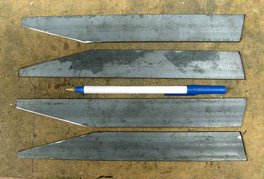
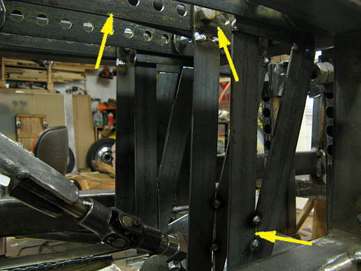
Four uprights were then cut and ......................
.................. .
.
........... welded to the top moveable pieces (top right arrow). They were tacked together at the bottom (bottom arrow). The top left arrow points to the main bracket pieces across the top.
.................. .
.
After they were tacked together they were finish welded.
.................. .
.
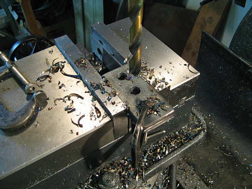
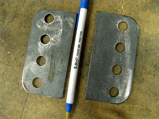
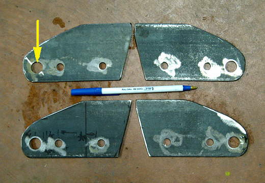
These pieces were made to go on the bottoms of the uprights. The large hole is for a bolt to go through that the pedal will pivot on and the two smaller holes to the right are for spacers that will hold the uprights apart.
.................. .
.
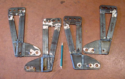
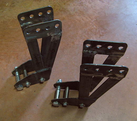
Now we have the finished uprights and......................
.................. .
.
............ this is what they look like in place.
.................. .
.
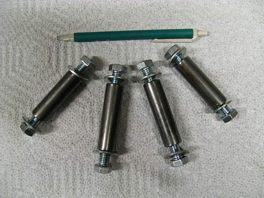
Four spacer were made from round stock. I drilled holes in the ends in the lathe and then tapped the holes for bolts.
.................. .
.
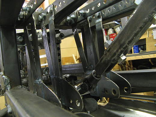
Here you can see how the spacers hold the uprights apart at the bottom and how the large pedal pivot bolt is located. The spacers will prevent a bind on the pedal bolt and make the uprights very ridged.
..............................................................Next
Page