...Return To Mine & Other Bonneville Car Construction Pages
.Previous Page...............B'ville Car Index Page.........................Next Page
...........................-- Steering Wheel and Shaft --
.................
O.K. let's get some steering on the car.....
.................. .
.
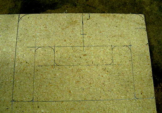
I had a small rough cut out of particle board wheel that I was using for ideas. Now I made a better one out of particle board. Here it is laid out prior to cutting. After trying it in the car the pattern...................
.................. .
.
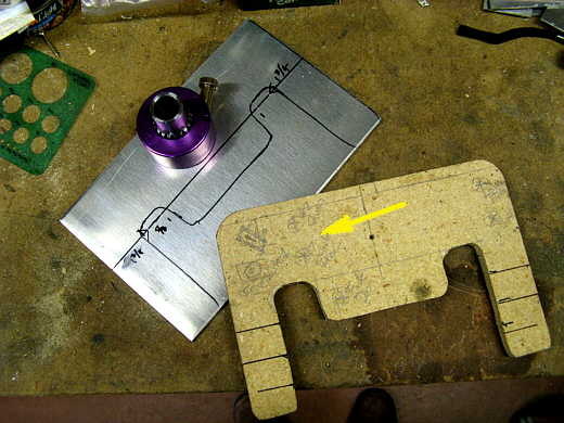
................ was transferred to a piece of scrap aluminum I had and ......................
.................. .
.
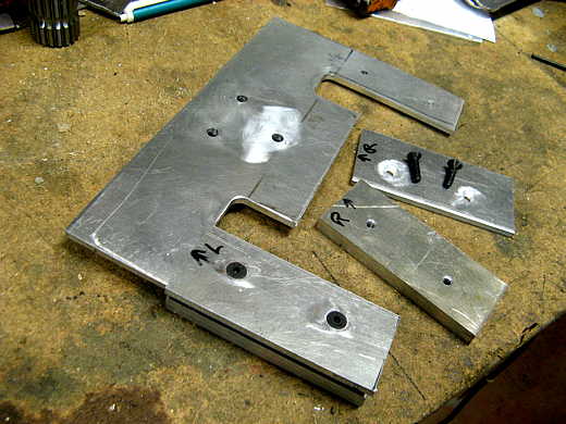
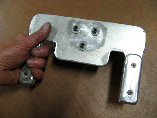
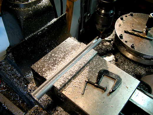
............ cut to shape with an end mill after the corners had been drilled out with a bit. I had put holes in for the quick disconnect and kind of butchered them up by a miss-calculation (arrow). They worked, but I wasn't happy with them so............
.................. .
.
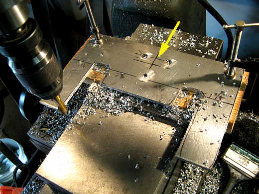
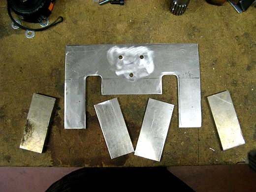
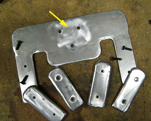
............. I welded the two top ones shut and drilled two new ones. Looks better even though you never would have seen them. Then two pieces of one thickness aluminum and two more of a different were rough cut to size to use as grips on the sides.
.................. .
.
The thicker ones were drilled and tapped for the bottoms and the two thinner ones were drilled and counter sunk for the tops.
.................. .
.
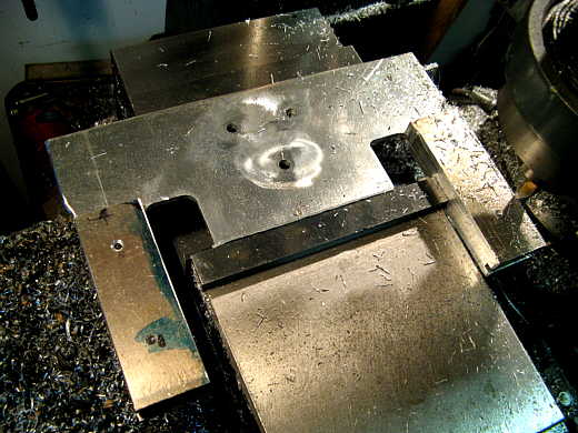
They were screwed into place and it was back to the mill to cut all the grips the same and to the final size.
.................. .
.
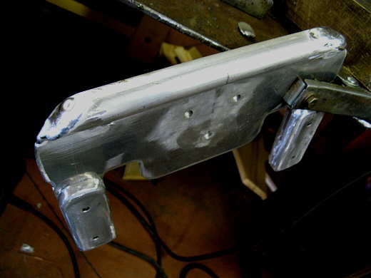
The arrow points to the two holes that I had fixed. Next the grips were ground to a more comfortable shape with the grinder and finished up with the air grinder.
.................. .
.
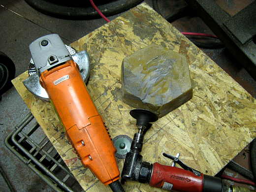
If you are not aware of this if you get some wax like in the picture and run your grinder across it (running) every couple minutes it keeps the disc from filling up with aluminum. I just started doing this recently after buying some wax from Fournier Enterprises . Try it, it works. A pound like in the picture is less than $8.00 and should last a long time.
.................. .
.
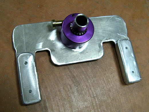
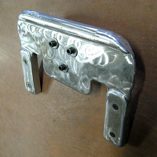
Here is the front side of the wheel. Later switches will be mounted on it to open the chute doors, fire the chutes, master elect. cut-off and up/down shifting.
.................. .
.
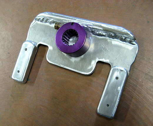
A view of the back side. It still hasn't been finished, but will be by the bottom of this page.
.................. .
.
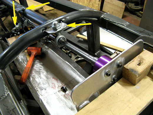
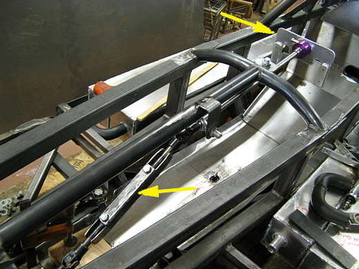
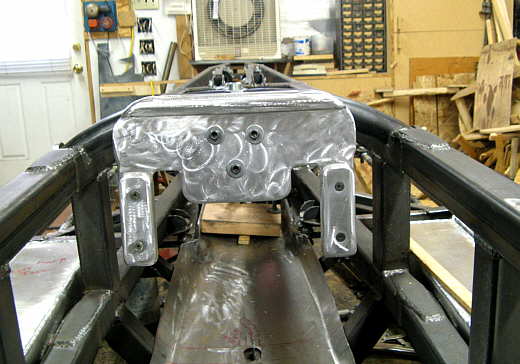
The steering shaft angles down from the wheel at a very slight angle about parallel to what will be the top of the car. Two mounts were made to hold the heims that it goes through (middle arrow and right arrow). Just past the middle arrow it angles down to the steering box (left arrow). There is a u-joint where it angles down and at the steering box. When you are in the car laying down the comfortable range where the steering wheel needs to be is fairly small. I wanted to make that adjustable for both myself, but in case someone else is driving the car. To do that I wanted be able to adjust the length of the angled part of the steering shaft area. If it was shorter then the top shaft would slide towards the front of the car and if it was longer the top shaft would slide towards the rear.
.................. .
.
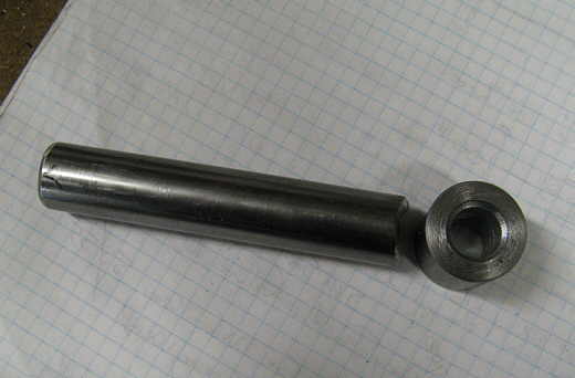
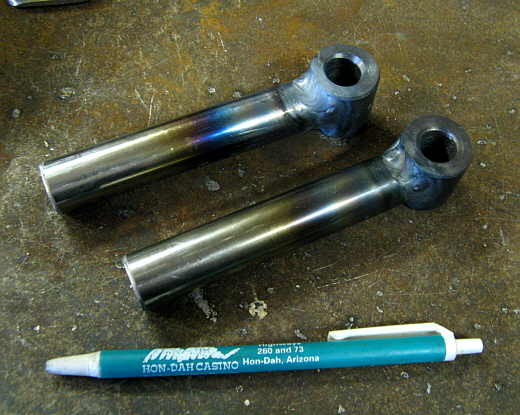
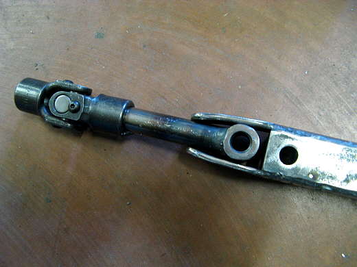
Here is a short piece of steering shaft that has been ground on one end for the bushing on the right that I made.
.................. .
.
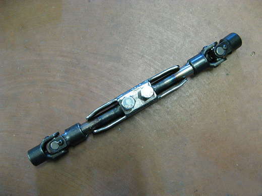
Two of these were welded up. One goes in the bottom u-joint and the other in the top u-joint.
.................. .
.
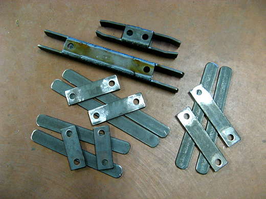
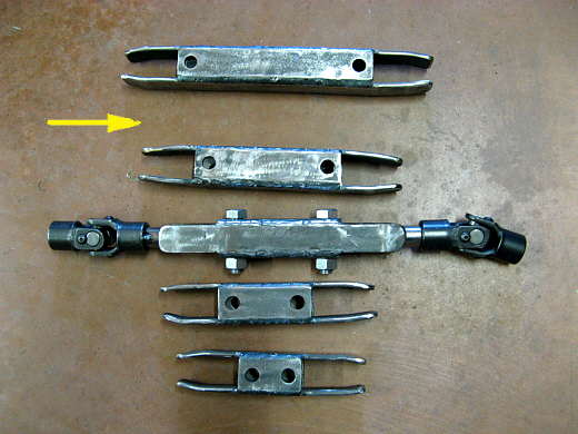
Next different length spacers/links were made that would connect the two pieces in the last picture . These were made with the mounting holes different distances apart in one inch increments. The very top one is finished the next one down has to have the ends bent in and the rest is for the other ones.
.................. .
.
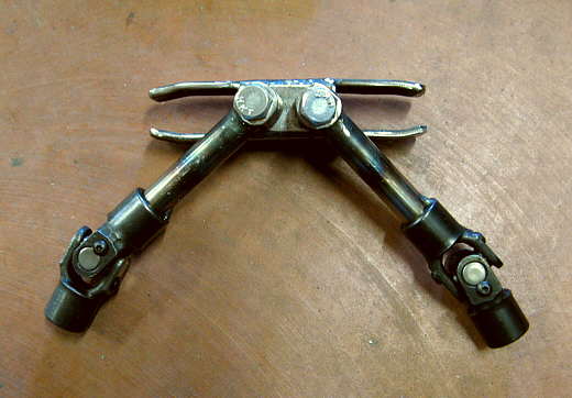
The reason for the extensions with the bends on them is I Just made a link the shafts would be able to rotate like in the picture.
.................. .
.
The extensions keep that from happening. and position everything in a straight line and turn it into a solid piece.
.................. .
.
The bends are out on the ends so that the steering shaft can be pulled back and then slid up and out of the assembly.
.................. .
.
Here are the completed links with one missing since I ran out of materials.
.................. .
.
Here the longest link is in place (left arrow) and the wheel is back and away from the cross-member ahead of it.
.................. .
.
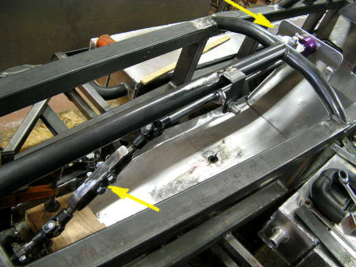
Here the shortest link is in place and you can see that the wheel is almost up to the crossmember. It just takes a minute to change these.
.................. .
.
Now back to finishing the wheel. It seemed plenty stout, but you know me, so I decided to make it stouter. I took a piece of aluminum tubing I had and milled a slot down it length and then..................
.................. .
.
.............. welded it to the top of the wheel and plugged the ends with weld.
.................. .
.
A few minutes with the grinders cleaned it up. The front and ..................
.................. .
.
................. the back and ........................
.................. .
.
............. the view over the wheel and down to the nose of the car. I'm really happy at this point how the steering works, there seems to be virtually no play, but the car isn't on the ground and going down the salt with the tire/wheels on it. We will know more at the first test.
..............................................................Next Page