...Return To Mine & Other Bonneville Car Construction Pages
.Previous Page...............B'ville Car Index Page.........................Next Page
......................................-- Water Tanks Part II --
.................
On this page I'll finish the cooling water tanks on the left side of the
car and part of the intercooler tanks on the right side. I needed to make some weld-in nipples for one end of the
tanks that I could slide radiator hose on. The water goes through one tank and out the end and makes a 180 degree
bend and back into the other tank and back through it to the outlet.
.................. .
.
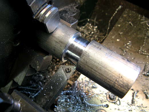
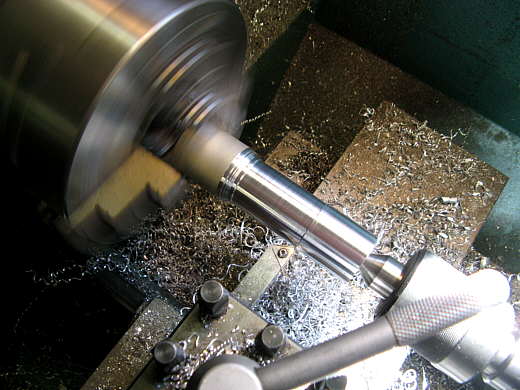
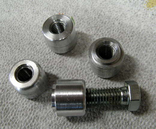
To make the nipples I used some solid round aluminum scrap that Hooley found for me. I could make two nipples out of one piece. The middle was turned down to the dia. that I wanted that would go into the tank end and be welded.
.................. .
.
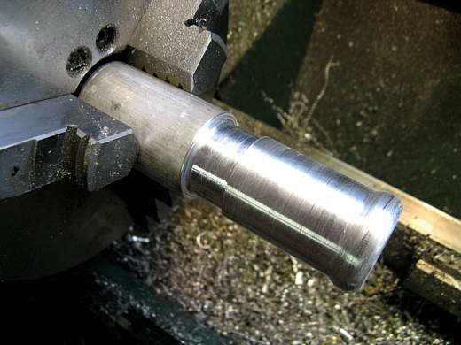
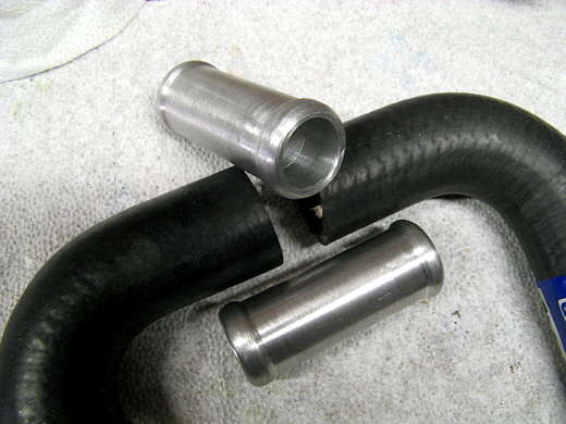
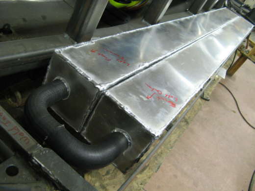
Next one end was turned down a little with a flange on the end and it was drilled out to 1 inch for it's entire length. 1 1/4 inch radiator hose..............
.................. .
.
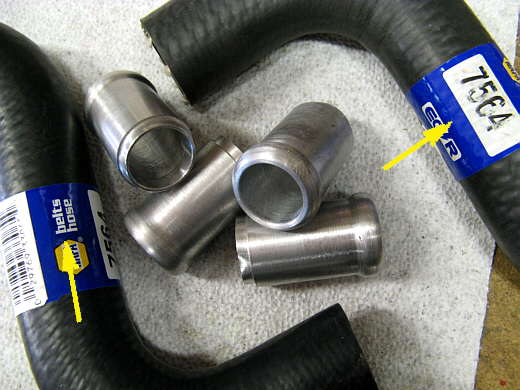
............ is used to make the 180 degree turn from one tank to the other. The hoses were cut where the arrows are to give me 90 degree bends. Since the hose was larger on one end than the other I could only use 1/2 of each hose, so 4 were required for the tanks on both sides of the car. Above are the 4 nipples that were needed.
.................. .
.
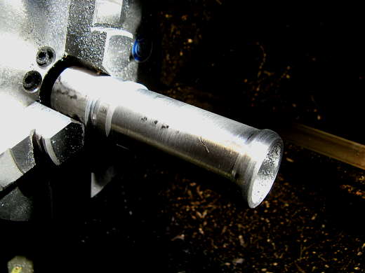
Next some couplers were made to join the hoses. This one is almost done and will be cut off by the chuck jaws. Again the outside was turned and filed and the inside was bored out to 1 inch.
.................. .
.
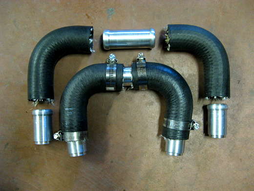
The finished couplers and...................
.................. .
.
............. an illustration of how the above parts will work. There are two sets shown for the cooling tanks on one side of the car and the intercooler cooling water tanks on the other side. Even though I won't be using the intercooler cooling water tanks now I thought I would make these parts while I was at it and before I forgot what I did. I'll finish the input/output, fill lines, and opening to put in ice in those tanks later when I have time.
.................. .
.
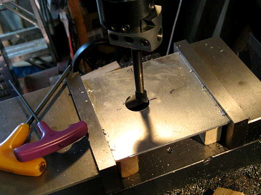
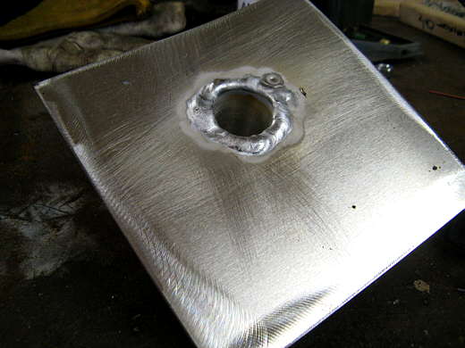
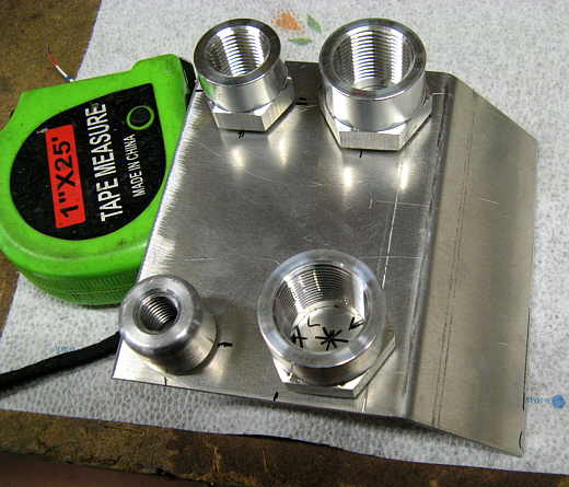
Pieces of .090 aluminum were cut to 5 inches by 5 inches for the end caps and drilled to 1 inch for a nipple. The nipple ends were a little over 1 inch, so I had to use the boring bar to take them past 1 inch (my largest drill size).
.................. .
.
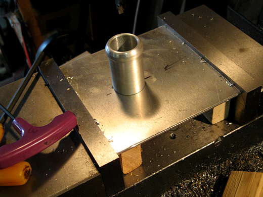
A nipple being test fitted after boring the hole.
.................. .
.
The nipples were then welded to the inside of the end cap and then...........
.................. .
.
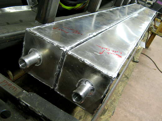
.......... to the outside of the end cap and the end cap was welded to the end of the tanks.
.................. .
.
The nipples are a little off center to work with the radiator hose curves.
.................. .
.
Next I turned my attention to the other ends of the tanks. First I machined ............................
.................. .
.
................. four pieces for drain plugs. They are stepped on one end to provide a place to weld them to the inside of the tank. They were tapped for a 1/2 inch drain plug bolt. I got some drain plug washers from the hardware store to use with these.
.................. .
.
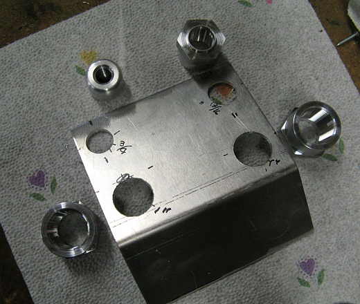
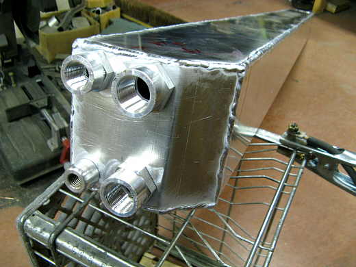
Next the other weld-in bungs were laid out on the tank end cap. In this view the bottom left is the drain plug. Bottom right is the outlet from the tank to the motor. The top ones are for fill lines that will also be expansion lines up to a surge tank. One extra fitting was welded on for whatever might be needed in the future, like maybe a temp sensor.
.................. .
.
holes for the bungs were then drilled into the end cap. Notice that these bungs also have a weld step in them. I didn't make these, but bought them as I wanted really nice threads in them.
.................. .
.
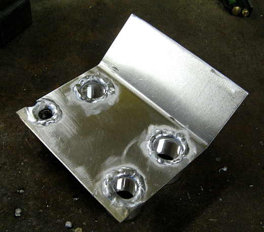
The bungs were then welded from the inside and...................
.................. .
.
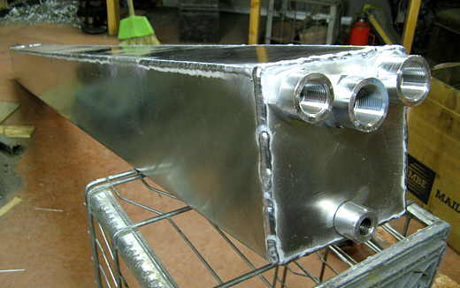
........... the end cap was welded on to the end of the tank. The angle cut on the end is to clear part of the frame in the car. This tank is the outlet tank and.................
.................. .
.
............ this tank is the inlet tank with the drain at the bottom and the inlet top center with the fill and aux. bungs on each side of it.
.................. .
.
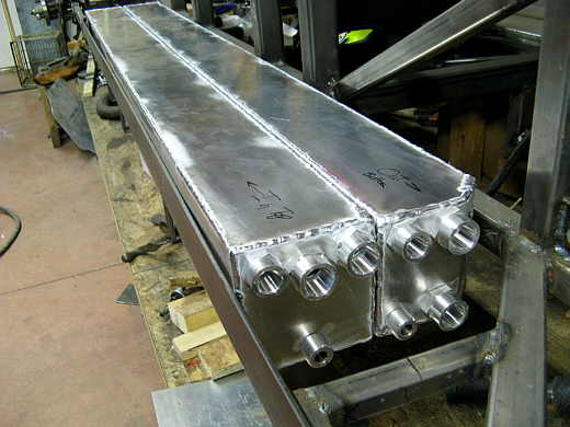
The two finished tanks in the car. Remember they look large, but are only 5 inches tall with a 10 inch width for both of them. Their total capacity is about 15 gallons.
.................. .
.
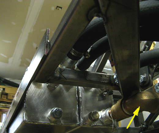
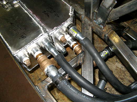
Here you can see the drain plugs with their washers and the arrow points to the outlet line on the bottom going to the motor.
.................. .
.
The inlet is the left line in the picture ( 1 inch ID input and output lines). The two smaller 3/4 inch lines are the fill/vent/expansion lines that go up to a fill/surge tank that you will see on the next page.
..............................................................Next Page