...Return To Mine & Other Bonneville Car Construction Pages
.Previous Page...............B'ville Car Index Page.........................Next Page
.......................................-- Chute Doors Part III --
.................. .
.
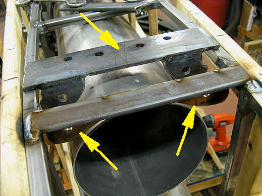
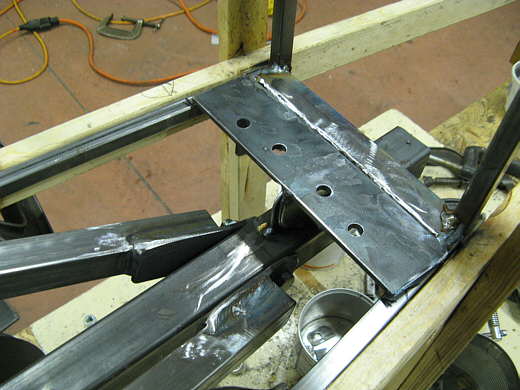
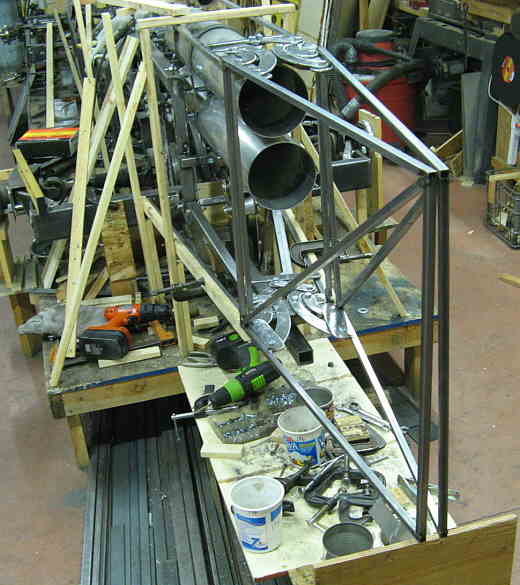
The top arrow points to the plate that the hinge assembly pivots/bolts to. It is slid back so you can see the mounting ears on the bottom of it. Later ears will be added to the top backs and will bolt to the sub-frame there. The lower two arrows point to two mounting ears that are part of the cross-member above them that is part of the sub-frame.
.................. .
.
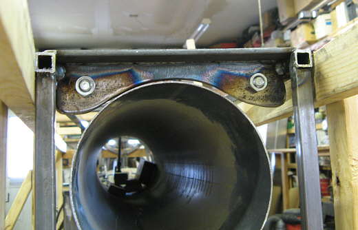
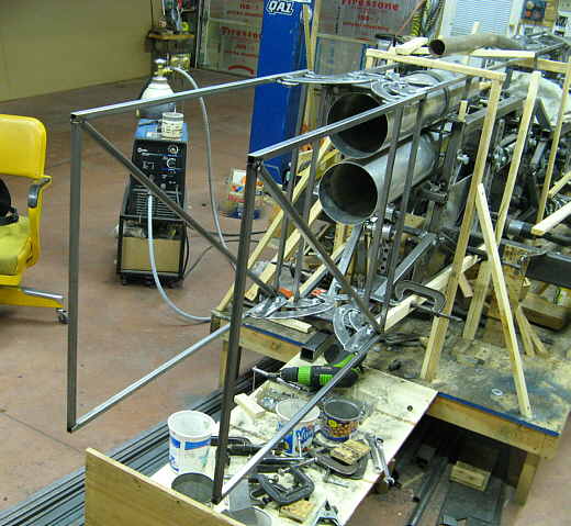
Another view from the bottom. This side still has to be welded.
.................. .
.
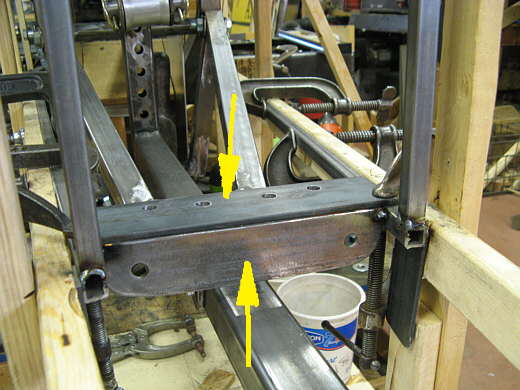
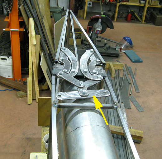
Next a similar operation was performed on the bottom for the hinge assembly that goes down there. The arrow points to the pivot plate for the hinge and it will be removable. It is clamped in place so that the location of the bottom cross-member can be determined and welded in. I started with the piece the bottom arrow points to with the mounting holes in it at each side.
.................. .
.
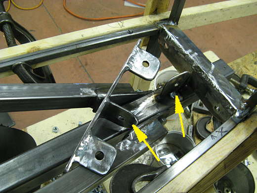
The removable piece is to the right. At this point you can see that a top piece was added to the bottom piece in the last picture. There is also a tab welded to the removable push bar (right arrow) and a corresponding tab welded to the removable pivot plate.
.................. .
.
Every thing bolted into position and............................
.................. .
.
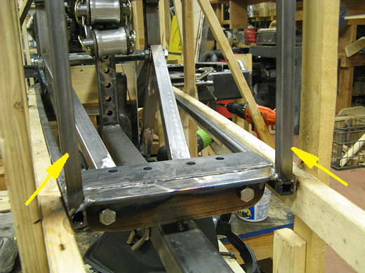
.......... a view from the other side. The arrows point to two uprights that were partially welded in. I had to cut them out and move them back just 1/2 inch for clearance with the hinge pieces. I should of just put small tacks on them.
.................. .
.
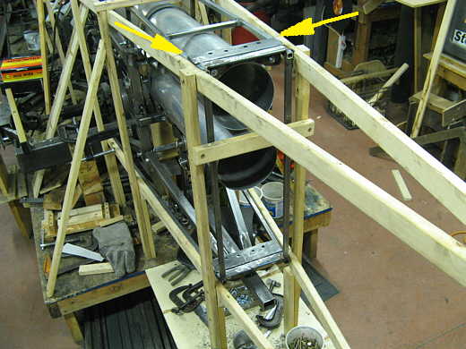
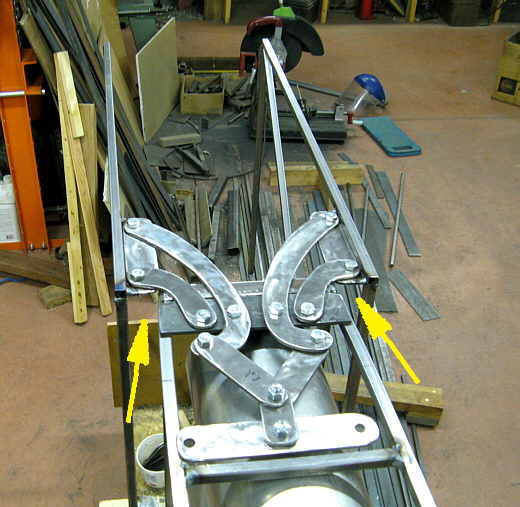
The arrows point to where two more mounting tabs will be placed to further bolt the removable pivot plate to the sub-frame.
.................. .
.
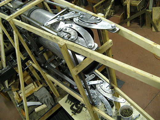
Now the hinge assemblies have been put into place.
.................. .
.
Two door frames have been started here and the picture shows the doors in the closed position.
.................. .
.
Looking at them from the other end. The arrow points to the upper lever arm that will pull the doors open. The right side will hinge on a pivot point near the cross-member that the arrow is on and the left end will be the end that is pulled on.
.................. .
.
Here the doors are in the open position.
.................. .
.
Notice that when they are open the fronts (two arrows) have swung away from the body leaving a gap (two arrows again) for air to enter. I'm hoping air will start to enter there and assist in opening the doors. When the doors are open their sides are very parallel to what will be the air stream. Hopefully they will be in a neutral position in relation to the wind, kind of like a weather vane. I've spent quite a bit of time on this and I'll have a lot more time into it, so I hope it works.
..............................................................Next Page