...Return To Mine & Other Bonneville Car Construction Pages
.Previous Page...............B'ville Car Index Page.........................Next Page
.........................................-- Chute Doors Part II --
.................. .
.
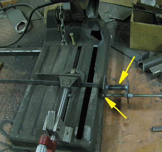
I need lots of tabs with holes in them to mount body parts and didn't want to measure them over and over again. I drilled a hole in the side of my chop saw and put a piece of "all thread" in the hole and held it with bolts on both sides of the hole (bottom arrow). Then I welded up a stop (top arrow) that can be moved along the all thread. It is off-set so that it can go onto the table of the cut off wheel for short pieces like I was going to cut. Here you see a piece of strap up against the stop and ready to be cut.
.................. .
.
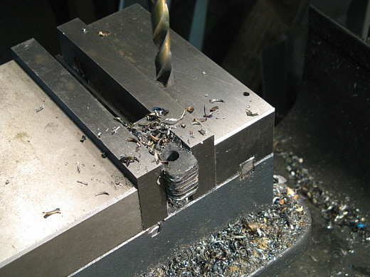
I cut about 20 short tabs and about 20 that were a little longer. I took groups of 6-7 of them at a time and drilled a 5/16 hole through a bunch at a time.
.................. .
.
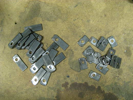
Here is a group that I finished drilling and hitting the ends with a grinder. The short ones weld to the frame and the long ones weld to the ends of square tubing for different length brackets.
.................. .
.
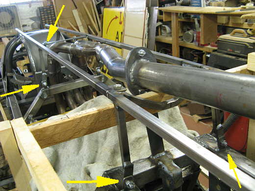
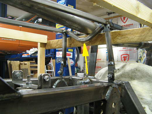
The arrows point to a number of the tabs in use on the frame and the ends of square tubing. The framework show here....
.................. .
.
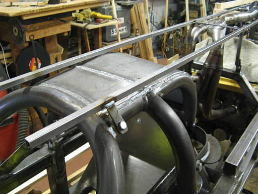
............. and here is goes back to the chute doors and will be used to mount the upper part of the body to when it is made. The part sticking out in front of the cage hoop will be trimmed back later.
.................. .
.
The arrow points to a cross-member that had to be bent to clear the exhaust. Note the loner tabs in use on the bottom ends of the square tubing and how they connect to the shorter ones welded to the frame. I wanted to be able to remove this bodywork frame and made it in come apart in different sections along it's length.
.................. .
.
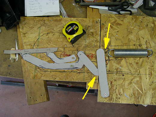
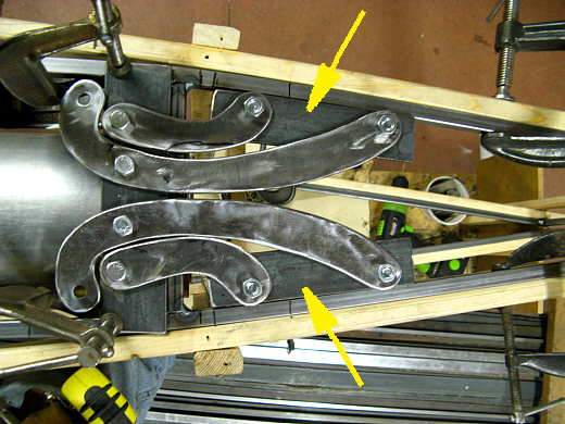
After mounting the sub frame I went back to work on the hinges for the chute doors. The top arrow points to a lever arm that works on the hinges through a short link (bottom arrow) and a longer link between the short one and one of the hinges. The second hinge just goes along for the ride. There will be another set of hinges opposite these and a second complete set at the bottom of the doors. The spring will pull on a bar that goes between the lever arm that works the top hinges and the one that operates the bottom hinges.
.................. .
.
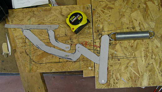
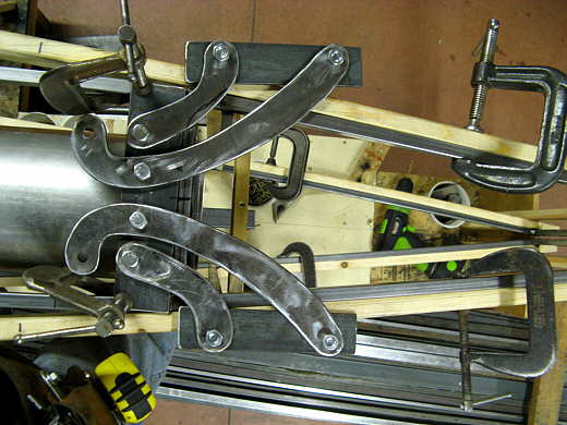
Here the lever arm has been pulled to the right and the hinges open the door.
.................. .
.
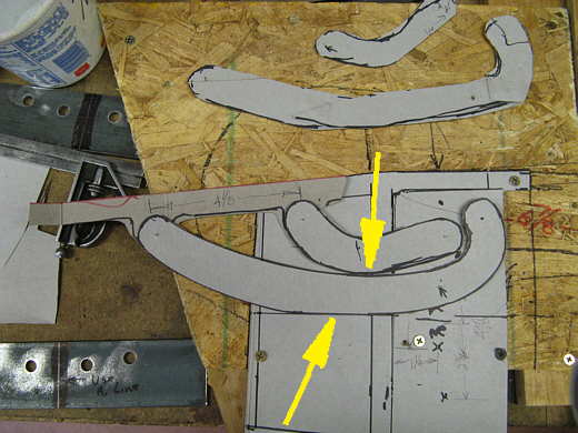
Feeling fairly confident that this whole scheme has a chance of working I tried to lay the whole mess out as accurately as possible. The big square shaped piece under the hinges and arrows is a full size pattern traced directly off of the hinge area on the car. Next I had to design the hinge pieces to clear each other (top arrow) when closed and to also clear the adjacent set opposite these. That is the reason for the center line above the second arrow. Thumb tacks were used for the pivot points.
.................. .
.
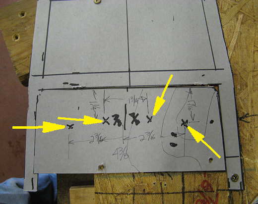
The arrows point to the position of the pivot points for the hinges on both sides. I took measurements for these points and .....
.................. .
.
............. transferred them to a piece of 2 inch wide strap that will be attached to the framework. I'm drilling through 4 pieces here. Two for the top hinges and two for the bottom hinges. If possible the hinges will be sandwiched between two plates so that the hinge bolts are in double shear.
.................. .
.
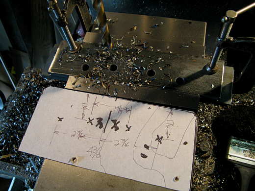
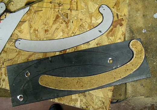
Next I took the new much more accurate hinge patterns and transferred their outlines to some 3/16 inch by 4 inch wide strap. I center punched the location for the bolt holes off of the patterns.
.................. .
.
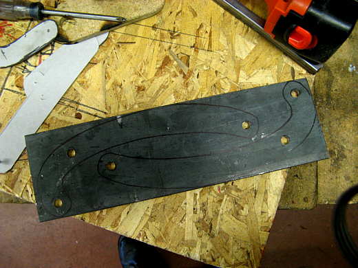
Then a piece of 3/8 inch particle board was cut slightly undersize to act as a guide while cutting these pieces out with the plasma cutter. You can see the location of the bolt holes in the paper pattern that I use to find the location of the holes in the actual hinges.
.................. .
.
After cutting with the plasma cutter and a lot of finish grinding I ended up with the top hinges. The arrows point to pieces that will be welded to the square tubing that will make up the framework of the doors.
.................. .
.
Here the doors are in the open position. At least the hinges are in the open position. The idea is the front end of the doors (to the left above) open first and then air can get in behind them and help to open the other ends along with the pull from the spring. When open the doors become parallel to the air stream and hopefully want to stay in that position. We will see. This whole idea could still go down a different road in the future if it proves not to work.
..............................................................Next Page