...Return To Mine & Other Bonneville Car Construction Pages
.Previous Page...............B'ville Car Index Page.........................Next Page
...............................-- Chute Mount and Push Bar --
.................. .
.
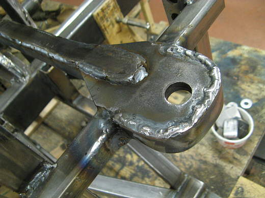
Tom reminded me of the high loads a chute can impose on a car, so I went back and worked on the parts that the chute attaches to. The plate in the picture with the hole in it was 3/16 thick. I added a second plate under the first in front of the square tubing. Then I ran a strap around the front of it and also welded another strap to the top of it running back along the 1 inch square tubing that goes forward and attaches to the frame near the motor.
.................. .
.
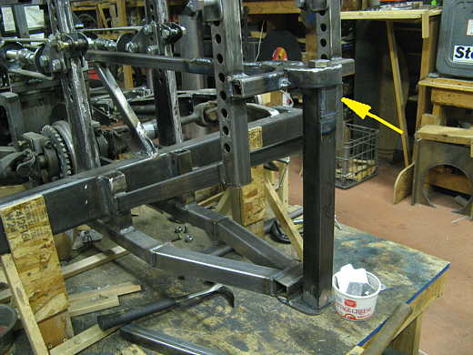
Next I changed out the 1 1/4 inch vertical square tubing for 1 1/2 inch square tubing and welded a tap on the top end (right side of the tube in the picture). I also welded the nuts a little deeper in the ends of the tube so that I could use a grade 8 bolt that wasn't all thread and had a shoulder on it. That way the bolt won't be in shear across the threads like it was before.
.................. .
.
Here the vertical bar is back in place. The arrow points to where the tab goes up behind the strap that wraps the top bracket. The tab lays on that strap, so now some of the load that would normally be all on the bolt is also on that strap.
.................. .
.
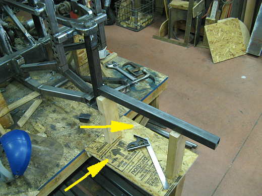
Here what will be the "push bar" is tacked to the chute "pull bar". The arrows point to diagonal lines on the table that represent projections of the body tapering in at the very back of the car. These angles are less than 7 degrees to help the air flow as much as possible. After the body is done a bracket and wheel will be attached to the end of this bar and the wheel will just barely stick out the back of the body. This bar needs to be triangulated into the rear frame as much as possible and that will be next. Also all of this has to be removable so that the fuel cell can be serviced directly in front of it (it is not in the picture and/or finished at this point).
.................. .
.
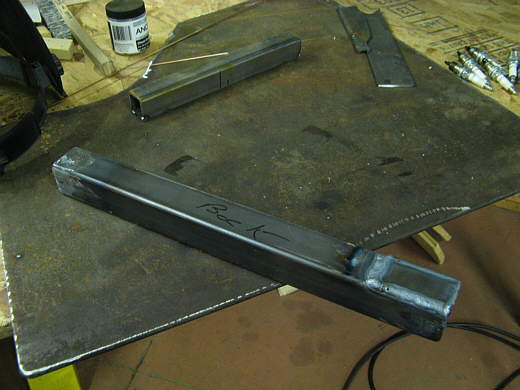
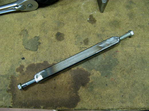
This square tubing had nuts welded into the ends. It is not large, compare it to the ratchet barely in the picture and it....
.................. .
.
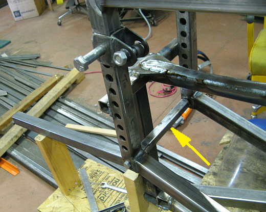
........ was place between the uprights that will locate the shocks (arrow) to space them and tie them together. Again it has to be removable to put the fuel cell in and out of the back of the car.
.................. .
.
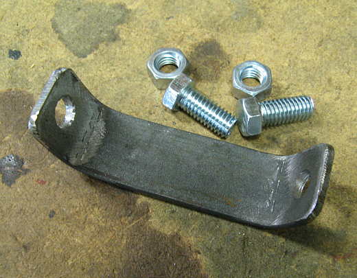
Next this bracket was made......................
.................. .
.
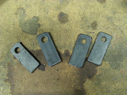
.......................along with these tabs.
.................. .
.
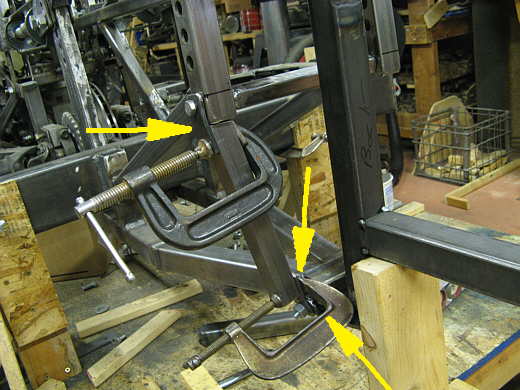
The bracket was welded to the very bottom of the frame and is just barely visible behind the C-clamp (bottom right arrow). The other two arrows point to two of the tabs that were welded to the ends of the vertical square tubing. Here C-clamps are holding the tabs to the tubing so I can weld them on.
.................. .
.
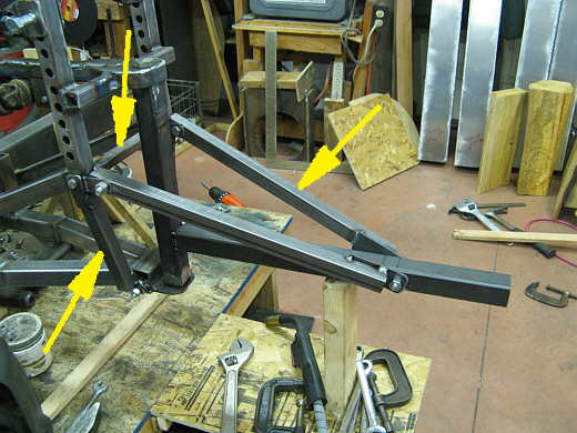
The first bar (top left arrow) and the lower vertical/diagonal bars (bottom left arrow and there is a second on
on the other side) triangulate the rear of the frame and help to make it a lot more ridge than before. I did this
so that the two pieces of square tubing going down to the push bar (right arrow) would have a solid foundation
where they attach to the rear frame.
..............................................................Next Page