...Return To Mine & Other Bonneville Car Construction Pages
.Previous Page...............B'ville Car Index Page.........................Next Page
......................................................-- Seat Part II --
The seat as finished before this page would have worked fine, but I wanted to finish it off a little better. I wanted to round the areas off by my legs and near the waist belts so there would be no sharp edges and it would stiffen the seat some.
................... .
.
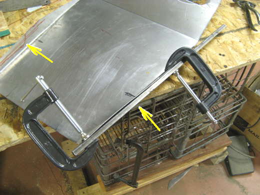
I started by marking a line about 1/2 inch down on the side (top arrow). Then on the back side of the seat and on the line I clamped a piece of square tubing (bottom arrow). A body hammer was then used to bent the area over at a 90 degree angle and flat on the square tubing.
................... .
.
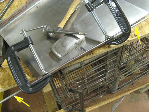
Next a piece of round rod (arrows) was clamped where the square tubing had been and using the hammer again the piece was rolled over the rod.
................... .
.
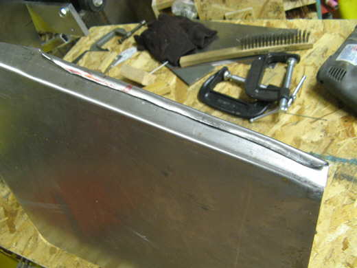
The the rod was removed and the hammer and dolly was used to move the piece into the side of the seat. Here it is about done except for a little more hammer work on the wavy sections.
................... .
.
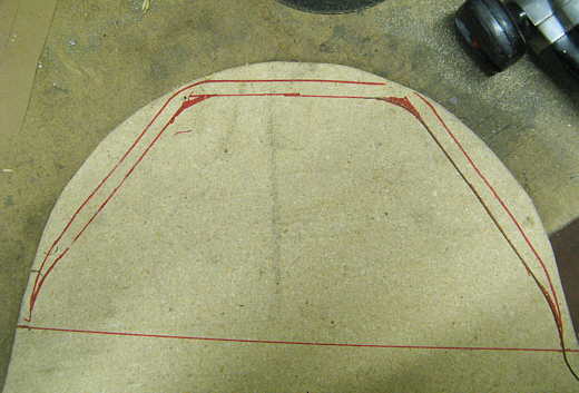
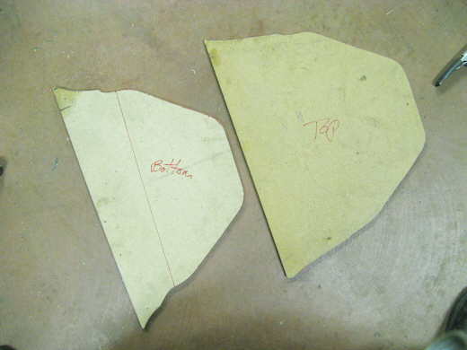
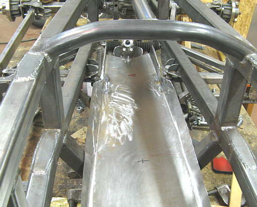
Next up was to roll the top part of the seat where my helmet will rest on a pad. I laid the seat on some particle board and traced around it (Outer line). Then I came in about 1/2 inch again and made a new line.
................... .
.
The piece was cut around the inner line and that piece was used to mark a second one and it was cut. They look different, but they are the same. Next one of the pieces was rounded along the edge with a router.
................... .
.
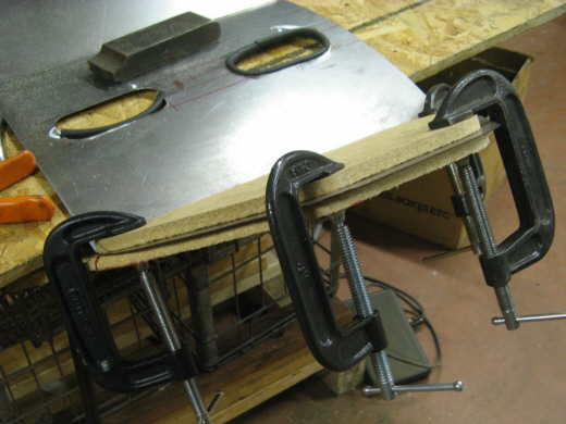
The pieces were clamped on the seat with the rounded edge one on the bottom and the other right above it.
................... .
.
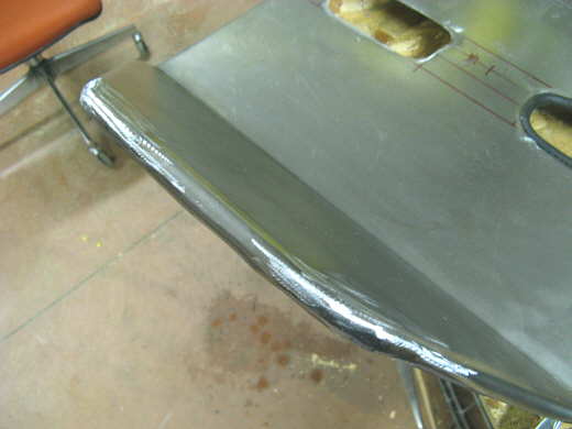
A body hammer was used to round the metal over the bottom form. The clamps were moved a couple times during this operation. The metal has no where to go in the middle of the corners so it just bunched up there.
................... .
.
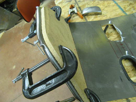
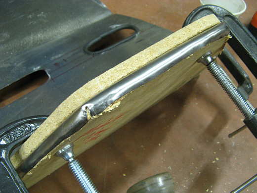
A cutoff wheel was used to cut off the bunched up metal in the corners. The gap looks big in the picture, but it was just over 1/16 inch wide. The welder was used to weld up the gap...........
................... .
.
............. in the corner and then if was grinded and smoothed with small disc on an air grinder. This is called hammer forming and I'd read about it, but had never tried it. It is really quite simple and easy to do. Now the top of the seat is a lot more ridge with this lip going around it.
................... .
.
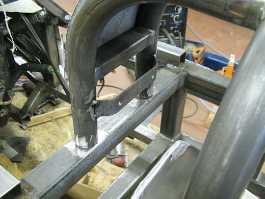
A brace was welded to the back of the cage and drilled to hold the top of the seat, which is laying in the car at the bottom of the picture.
................... .
.
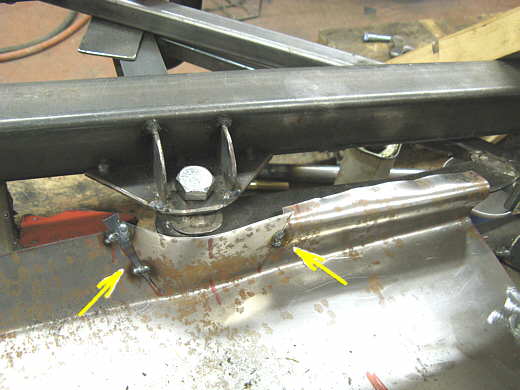
The front half of the seat down by the driver's feet area had to be modified to go around a steering pivot point. It was cut and then bent into rough position and tacked back together (both arrows). The left side require that a small filler piece be used to fill a gap there that was the result of the new shape.
................... .
.
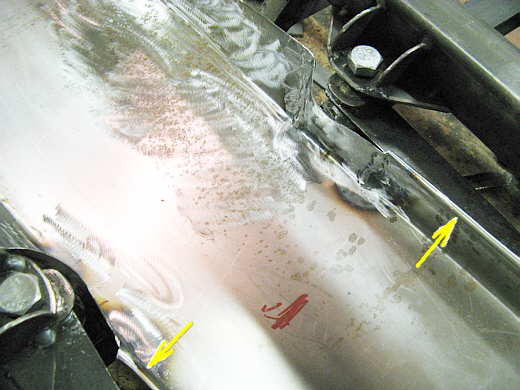
The piece was welded up and ground down fairly well and the forward areas were also rolled over to finish them off (arrows).
................... .
.
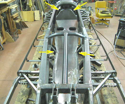
The front half of the seat it is held down on the front by a bolt and the other end............
................... .
.
........... at the middle of the car is trapped under the back half of the seat assembly by the lower arrows. The lower arrows also point to where the rear portion of the seat is bolted to a tab on each side of the cage. The upper arrows point to where the top of the seat is bolted on. So now the driver has a place to take a nap.
..............................................................Next Page