...Return To Mine & Other Bonneville Car Construction Pages
.Previous Page...............B'ville Car Index Page.........................Next Page
..............................................-- Water Tanks Part 1 --
The car will have two connected tanks for cooling water on one side of the car and two connected tanks for intercooler ice water on the other side of the car. This will give me a little over 15 1/2 gallons of cooling water and a little over 15 1/2 gallons of intercooler cooling water for when I add a turbo. This is overkill for the 750cc motor in the car now, but I hope it pays off with a turbo charged Hayabusa motor later.
................... .
.
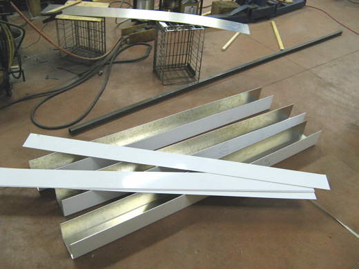
As I mentioned a few pages back I went down to Phoenix a couple weeks back and hauled a motor and transmission down to Sparky and brought aluminum back for Tony, Phil and myself. I got two sheets of .090 5052 aluminum for myself and while I was at Phil's on the way home we sheared them at 6 foot. I left the 4 X 6 foot pieces with Phil and he later took them to a place that had a big enough shear to shear the 6 foot long pieces into four 15 inch X 6 foot long pieces and five 5 inch X 6 foot pieces. The same place bent the 15 inch wide pieces into 5 inch X 5 inch X 5 inch X 6 foot long "U-shaped" channels. This is all shown above after I got it back from Phil. This will give me my 4 tanks (two for each side of the car).
................... .
.
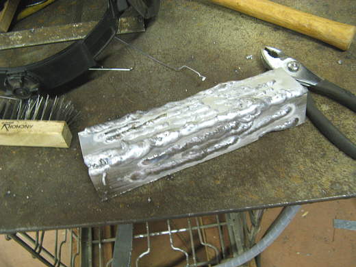
Now the big unknown. Could I actually weld these into tanks and not completely screw them up. I'd been welding steel with my new tig for a while now and was getting pretty good, but hadn't welded aluminum yet. I decided I'd better practice, so I cut some strips of the .090 5052 and tried to weld them together like I would have to with the tanks. The above mess was after trying for an hour or so. I could get the stuff together, but not in a very pretty fashion. I decided to move on to the tanks anyway and practice on the real thing. I could always point the welds down in the car where no one could see them. The welds weren't pretty, but I didn't think they would leak.
................... .
.
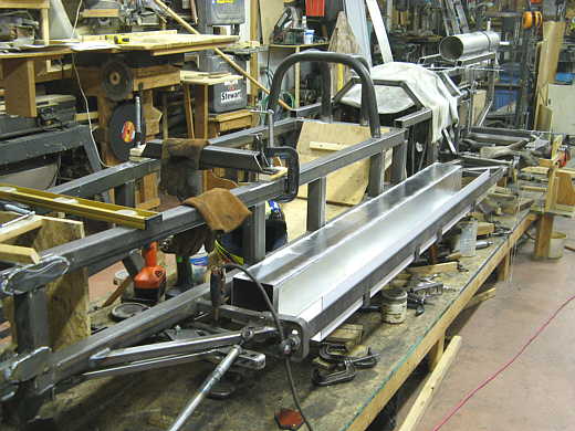
I cut a piece of wood 5 inches X 5 inches and put in in the far end of the tank where the clamp is. I cleaned the weld area good with a stainless brush and tacked the tank on the near end and a couple places further down.
................... .
.
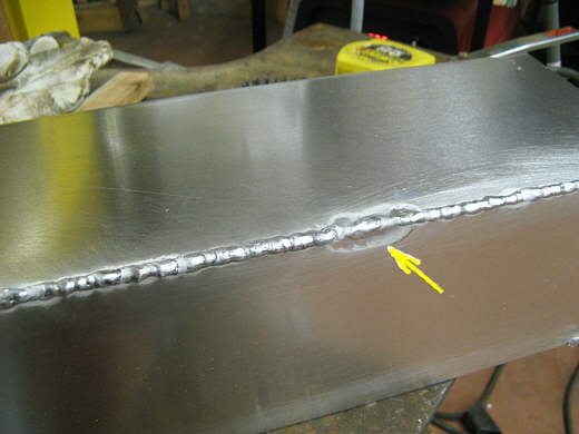
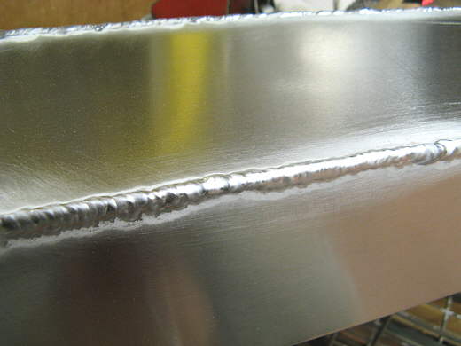
I was surprised to find that welding the real thing was much easier than the practice pieces. I think that was because I could clamp these together to get a good tight joint to weld. The small pieces had been hard to hold together and there were small gaps between them. This picture shows the results just a foot or so down the first tank. Not bad, but I had a few problems like where the arrow is pointed to. You can also see in these pictures where I brushed the pieces with the stainless steel brush.
................... .
.
By the time I was a couple feet down the first tank I was getting real happy with the welds. Not great, but not bad considering I had just started welding aluminum a couple hours before. I'd like to take credit but I'll give 90% of the credit to the welder. I can't say enough how great a welder this Lincoln Precision Tig is and would recommend it highly to anyone. If I can weld aluminum with this welder anyone can. I love my Miller mig and had a hard time ordering the Lincoln, but I'm so glad I did.
................... .
.
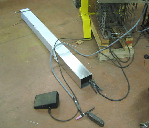
Here I am working down the tank. I was pulling the protective covering off ahead of the welds. On the other tanks I just removed it before starting and tacked them all the way down before doing the finish welds. By the time I got to the last tank it was taking about 1 hour to weld the 12 feet of total welds for each tank minus the end caps.
................... .
.
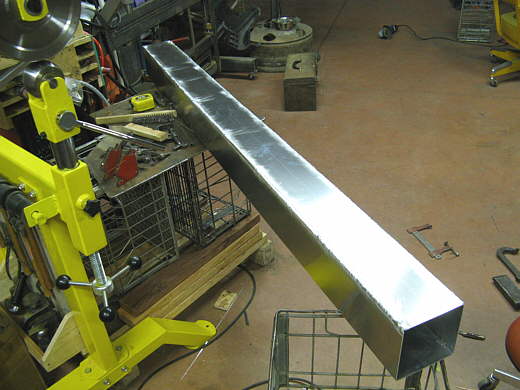
Here is the first tank finish except for the end pieces. I need to make threaded bungs and weld them into the end pieces before I weld them into the ends of the tanks.
................... .
.
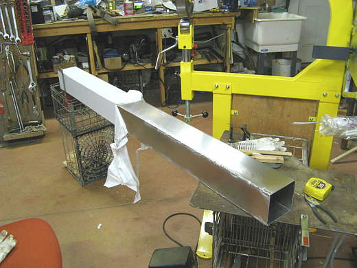
Here is the first finished tank in the side pod next to an unfinished one.
................... .
.
Another view. You can see I had the cage started at this point also and Phil would be over the next day. You can also see the temporary cross member on the top of the frame rails with a glove on it and next to it. This was the one I moved forwards and backwards along the frame rail to find the right place for the final one shown on the page before this one.
................... .
.
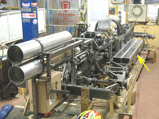
Phil came over on Saturday, went home that evening, and came back on Sunday (130 miles round trip each day. He wants me to move the shop closer to his place). The second day he was over he made the side pod (arrow) for this side of the can and he also welded up one tank, shown above next to the one I welded.
................... .
.
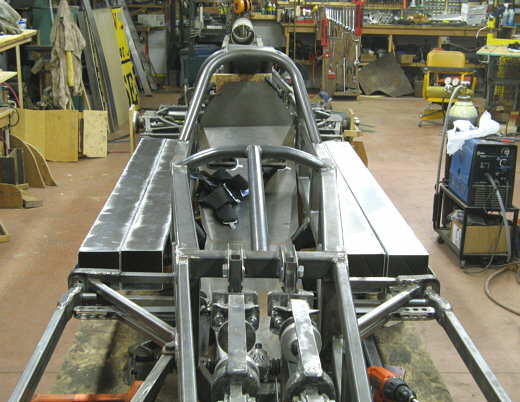
The day after he left I welded the two tanks for the other side of the car. Water will enter a tank at the rear of the car and go forward in the tank to the front of the car. There it will reverse direction in the tank next to it and return to the rear of the car and exit to either the motor or intercooler depending on which set of tanks we are talking about. Phil said the car reminded him of an Indy style car looking like this.
................... .
.
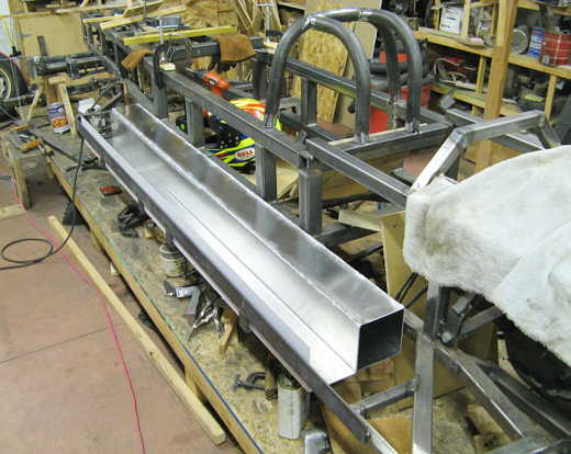
It is hard to get a feeling for size in these pictures, but remember the tanks are only 5 inches tall and the pair of them on one side of the car are 10 inches wide.
................... .
.
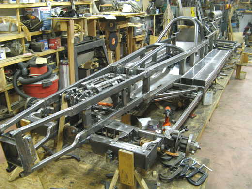
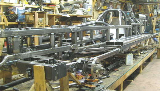
Here you get a little better feel for how the suspension, front and rear cross members, axles, and tanks are all in the same 6 inch high vertical plane for the whole length of the car on each side.
..............................................................Next Page