...Return To Mine & Other Bonneville Car Construction Pages
.Previous Page...............B'ville Car Index Page.........................Next Page
..................................-- Chute Tubes & Push Bar --
................... .
.
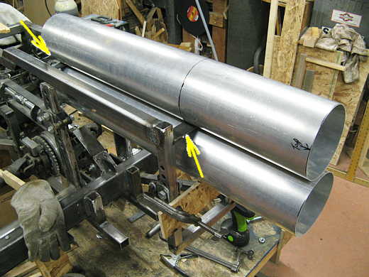
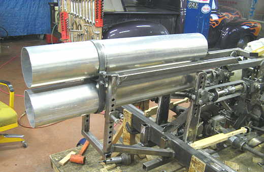
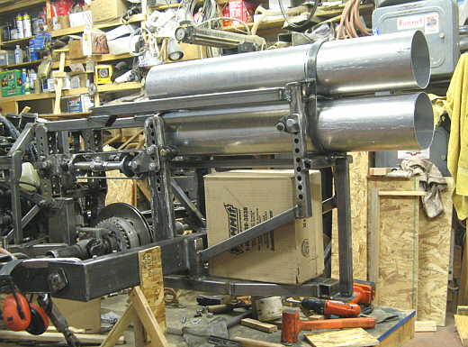
My good friend Jim Tafoya who lives in Farmington, NM came up with these two aluminum tubes for me. Bob Stroud recommended 6 inch by 36 inch tubes and said that would give enough room for about any chute he might build for me. I put two pieces of strap between the upper frame rails (both arrows). The one to the left has a hole in the middle of it and there are holes in both of the chute tubes. A bolt secures the two tubes to the piece of strap. I wanted the insides of the tubes from the back to the rear opening to be smooth, so I couldn't bolt the tubes to the strap on the right (rear of frame). So I .....
................... .
.
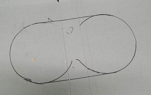
............ devised another plan of attack. Using a cereal box opened up a line was traced around the back of the two tubes. Using that as a pattern a .....................
................... .
.
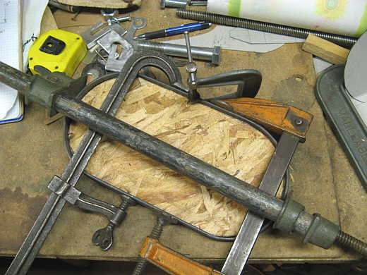
......... piece of wafer board was cut to that shape. Next some steel strap was wrapped around the pattern and the ends welded together.
................... .
.
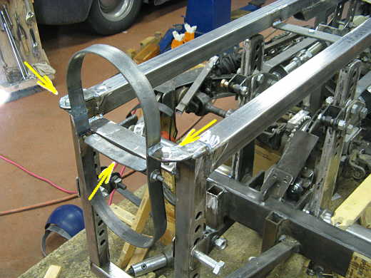
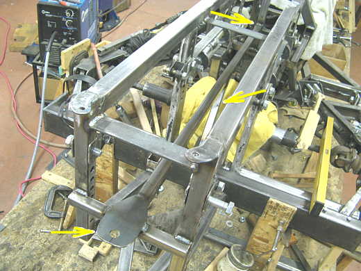
Two tabs were welded on the rear of the frame (upper two arrows) along with some short tabs to the previously made strap. The combination of tabs located the chute holder to the frame and in position. A cross strap was added to the middle with cut off bolt shanks welded to it. This strap goes between the two tubes and is drawn in to firmly hold them in place. Actually I tightened this strap to clamp the tubes and then located the tabs that I already mentioned.
................... .
.
Here is the finished assembly. I still have to make rear doors for the tubes and a mechanism to open them. The tail of the car will also be closed which will necessitate making an opening means for the rear before the chutes are deployed.
................... .
.
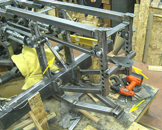
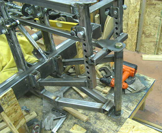
Next came making a pull bar for the chute lines to be anchored to. We ( Phil Alexander came over and helped me for 2 days -- He has car 2727 ) started by welding in a cross member right below the bottom chute tube and welded a tab to it with a 3/4 inch hole in it (bottom arrow). At the same time a piece of square tubing was put in from the tab/cross member forward and tied into the frame further forward (top arrow). In addition a diagonal brace (middle arrow) was put in between the new horizontal square tubing and the rear cross member below it to also tie that in better.
................... .
.
You can see the new diagonal piece better in this view (left arrow) It goes down and ties into the disc brake bracket and rear crossmember. The bottom frame rails were extended and brought together in a "V" shape and a tab with another 3/4 inch hole welded to them (bottom arrow). Next was the fabrication of a bar to go between the upper and lower arrows on the right.
................... .
.
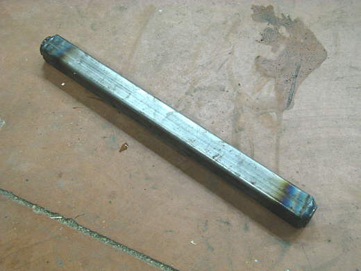
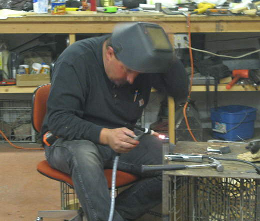
I took 2 3/4 inch nuts and turned them on the lathe for about 2/3's of their height so that they were round and would fit inside of this square tubing. They were placed in the upper and lower 3/4 inch holes and we measured between them to get the tube length and then Phil tig welded the nuts into the ends of the tube.
................... .
.
Here Phil has just finished welding in one of the nuts and the metal is cooling. Phil's main livelihood is building street rods (GP Autocrafters) and customs with an emphasize on chassis, drive train, and wiring. Last year he put a new frame and running gear and reconditioned the Barbee Boys roadster for it's new owner.
................... .
.
Here the bar is put into place with 2 grade 8 bolts. A bracket will be made that can slide up and down the bar to some extent to vary at what height the chutes pull on the car. The chute lines will attach to the moveable bracket. A push bar will be attached near the bottom of this bar.
................... .
.
The cardboard box represents where the gas tank will be located. The reason that the bar we made is removable is so the gas tank can be slid in or out of it's location.
................... .
.
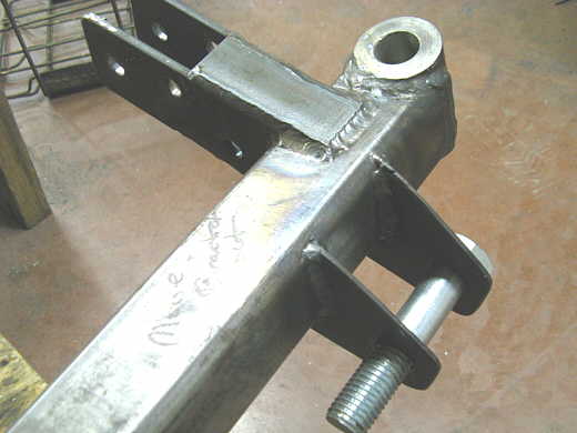
While Phil was over and at times waiting for me to make up my mind how we would make something he went ahead and finished welded some of the front suspension pieces. Here he had made a tab and welded it onto the bracket at the rear of the axle that the locator bar attaches to. Next and not shown he welded up the bracket at the front of the axle where the lever arm rides on a 3/4 inch bolt.
This was the first help that I've had on the car since I started and it was nice having someone else in the shop with me. Especially someone as competent as Phil
..............................................................Next Page