...Return To Mine & Other Bonneville Car Construction Pages
.Previous Page...............B'ville Car Index Page.........................Next Page
......................-- Finish Some Pieces/Stringing the Car --
................... .
.
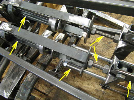
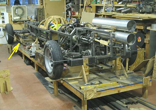
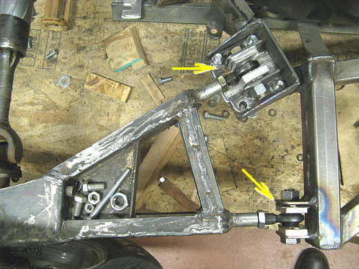
The front spring pockets shown above will have springs in them where the far left arrows are. One end of the spring will be on the aluminum spacers you see and the other ends of the springs will be to the left end of the bucket area. To raise the car to ride height the left end of the bucket will be pulled to the right in the picture compressing the spring. The two top arrows on the right side point to all thread that is normally used for items like vises. It is 5/8 inch in diameter and uses special nuts that match the threads. The all thread goes through uprights bottom right arrow. By turning the nuts on the all thread the bucket is pulled to the right. Once in position two grade eight bolts (one shown by middle bottom arrow) will hold the bucket at the desired position. Instead of having all different length bolts I decided to use long ones and make different length bushings that would make the bolts the right length. The bottom middle arrow points to one of the bushings..................
................... .
.
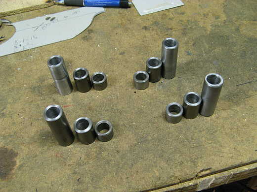
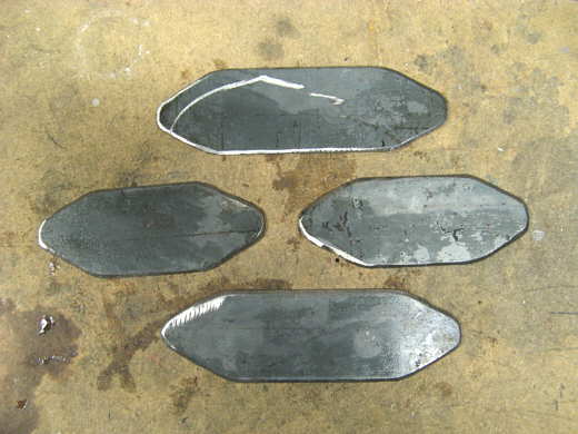
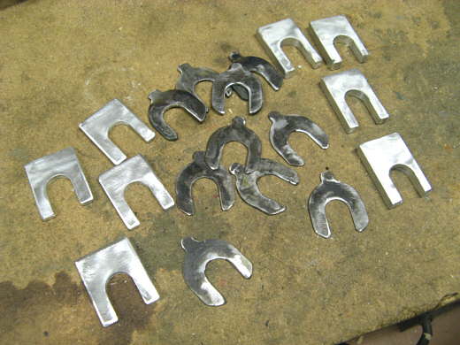
Here are the different length bushings. One group for each of the four bolts. I made these on the lathe with some cold rolled steel that I drilled 5/8 inch holes through.
................... .
.
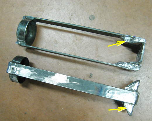
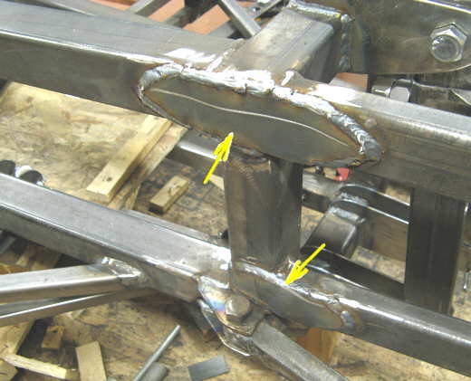
I also finished reinforcing this part of the spring bucket assemble as shown by the arrows with additional bracing and welds.
................... .
.
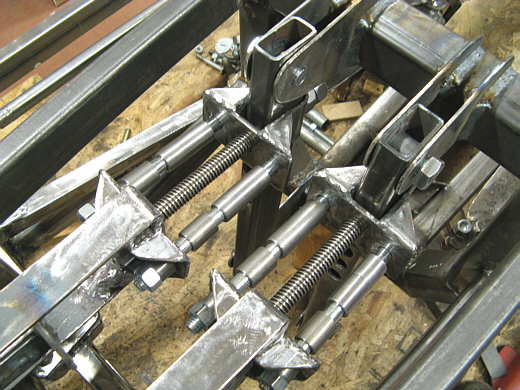
Here are the pieces in place. Each of the bolts has the extra bushings stored on them between the buckets and the frame upright.
................... .
.
Next these plates were cut out of 1/8 inch plate and.......................
................... .
.
.......................welded across some of the frame members to tie the front frame into the cage area.
................... .
.
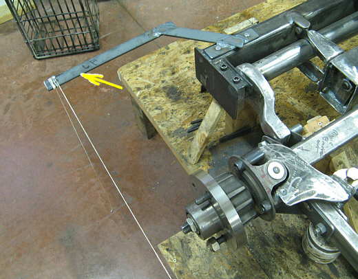
Up to this point I have stringed the car to align the front and rear wheels/tires with some temporary wooden pieces (bottom arrows) at the back of the car and in front of the car. I decided to add some pieces to the car itself that would allow me to string the car anywhere. Here you can see one with the string now attached to it. The right top arrow points to where it can be bolted to the rear cross member.
................... .
.
On the front I made a similar piece. They will only be bolted to the car when needed. The screws that locate the strings are the same distance from the centerline of the car on each side at the front and back.
................... .
.
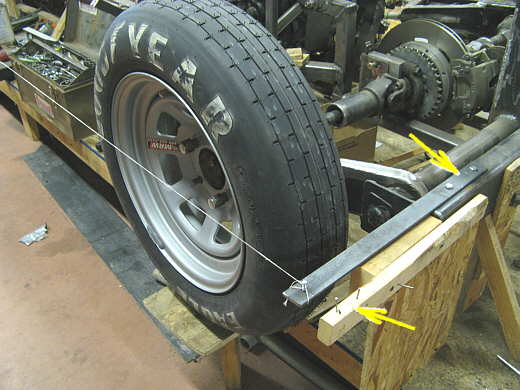
With the string (arrow) in place I can measure from the string to the front and back of the tires to see if the tires are in alignment or I can toe them in if needed. The camber is checked with a level that is placed up and down on the tire. I can also see if the tires/wheels are the same distance from the center line at the back and front of the car so that they are running in the same track.
................... .
.
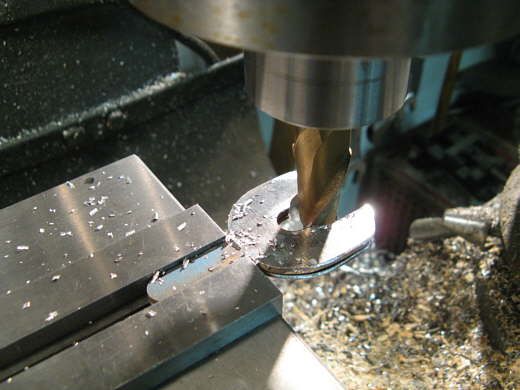
The back a-arms are aligned with shims. Here I am milling some wider slots on some shims I had.
................... .
.
I also made some out of different thickness pieces of aluminum.
........................ .
.
Way back in the construction I used pieces of wood for spacers (arrows). Now those........
................... .
.
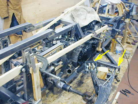
...................... have been replaced with the shims. The number of shims on each side of the heims move the a-arms and attached wheels/tires in or out from the center of the car. By screwing the hemis either in or out will change the toe on the rear wheels/tires. The top heim (top arrow) is attached to a plate that has shim plates under it. Raising or lowering this heim changes the camber of the rear tire wheel. For more on the a-arms you can look back on the main menu for the build.
..............................................................Next Page