...Return To Mine & Other Bonneville Car Construction Pages
.Previous Page...............B'ville Car Index Page.........................Next Page
...............................-- Finish Front Shock Mounts --
................... .
.
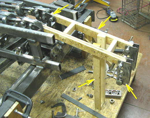
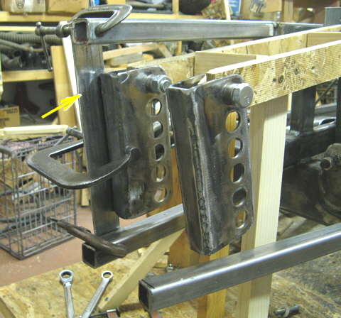
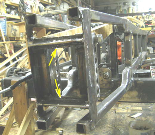
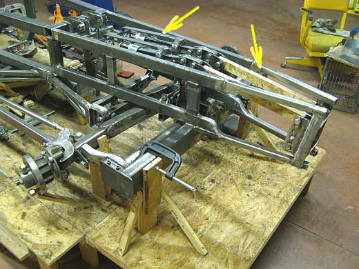
Back on pages 71 and 72 I made the shock bracket that attaches to the lever arm (left arrow) and the one that attaches to the frame (bottom right arrow). On this page we will locate the right one by extending the frame out to it. I cut some particle board and drilled holes in each end (top right arrow) to represent the shock length when it is in the middle of it's travel. I supported it so that it was 90 degrees to the lever arm with the lever arm in the middle of it's travel with two uprights (bottom left arrow).
................... .
.
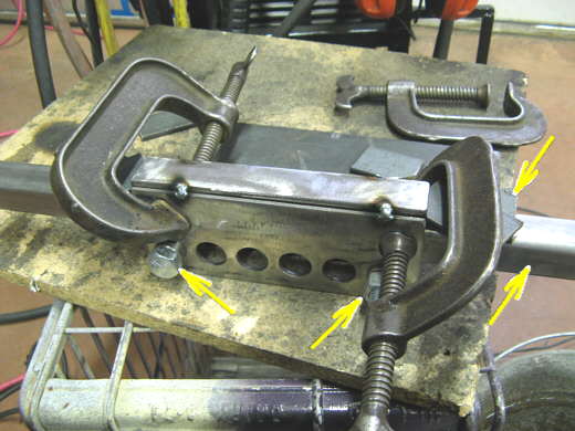
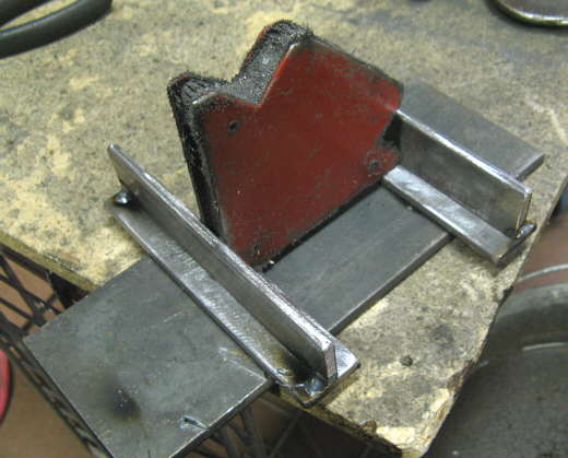
I took the brackets for the frame end of the shocks and cut a piece of strap and welded it to them to close the back of them in. They will be 1 inch apart so a piece of 1 inch square tubing was clamped between them (bottom right arrow). The strap sat on two bolts (bottom middle and left arrows) that went through the brackets. I shimmed the strap up into position with some scrap (top right arrow) on both ends and tacked it together with the mig welder.
................... .
.
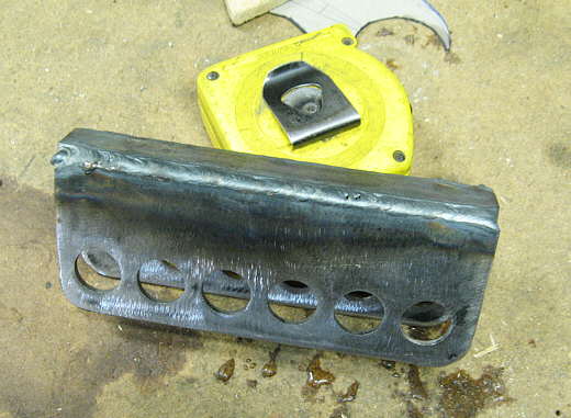
Then the piece was finished welded with the tig welder.
................... .
.
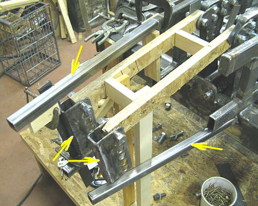
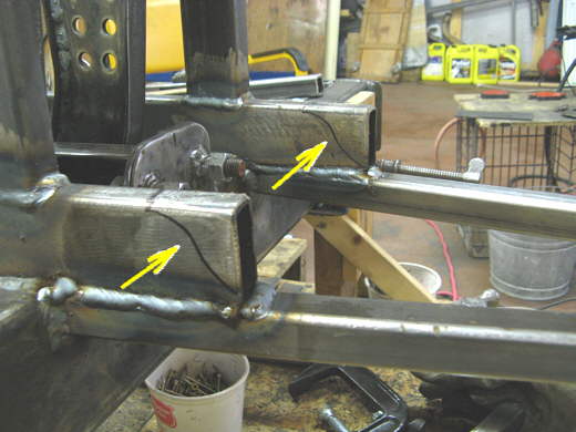
The two brackets were swung into position parallel with the lever arm and at right angles to the shocks. Two bottom frame rails of 1 X 1 X .120 square tubing were use to extend the frame out on the bottom (bottom right arrow) and on one side at the top (top arrow). They were positioned to be above and below the brackets.
................... .
.
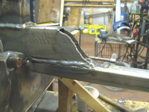
Strap (arrow) was clamped to the bracket and lower and upper frame rails and then tacked into position. This was repeated for the bracket on the right side in the picture.
................... .
.
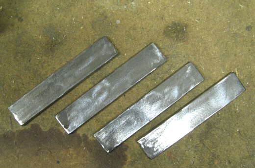
To tie the front of the frame together two more pieces were made. I started with the four pieces above in the picture.
................... .
.
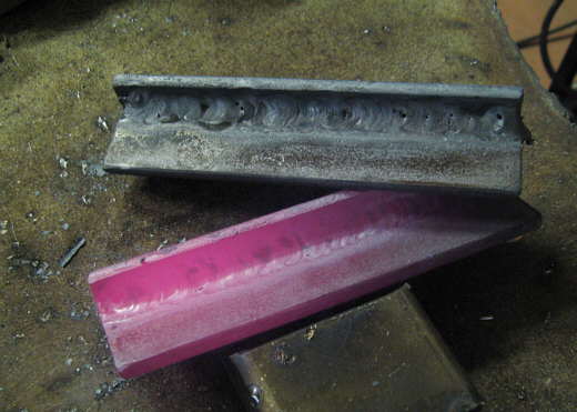
They were held together to form a "T" shaped piece and tacked in that position with the mig.
................... .
.
Using the tig they were then finish welded together. Guess which one was the last to be welded??
................... .
.
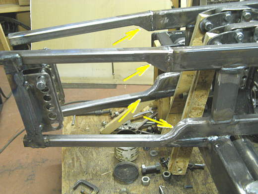
Next they (both arrows) were welded across the front of the frame between the vertical straps that hold the shock brackets. The shock brackets were also welded to these new pieces.
................... .
.
I wanted to clean up the areas where the frame stepped from the 1 X 2 rectangular tubing to the 1 X 1 square tubing. I made a little pattern and traced it onto the rectangular tubing (arrows).
................... .
.
Then using the plasma cutter the ends were cut off.
................... .
.
Strap was welded in on the top side and the welds ground down smooth (bottom two arrows). Grinding these welds has no structural consequences as this is a non stressed area. All of the pull or push on this frame extension from the shock will be pretty close to parallel to the ground. Just at a slight angle. To clean up the top I cut some square tubing so that it had angles on both ends (into a V shape) and welded them under the square tubing on the top frame rail (top arrows).
................... .
.
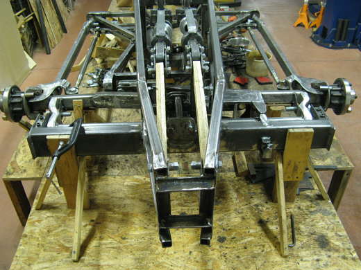
The finished front suspension with the shocks on the right and the spring buckets on the left. You can also see that besides tapering in the last addition to the frame also tapers down a little on the top rails.
................... .
.
A view from the front. The body won't have the angle of the frame rails, but will flow outwards from the front to the middle of the car and then flow back inwards to the very rear of the car. It will be very close to the frame rails though.
................... .
.
At the present the car goes from the front of the build table to the rear of the table and the table is 18 feet long. The finish car will probably be around 22 feet long. The total frontal area minus the wheels and tires should be about 5.3 square feet. That includes the main body and the pods that will cover the suspension and axles out to the wheels/tires.
................... .
.
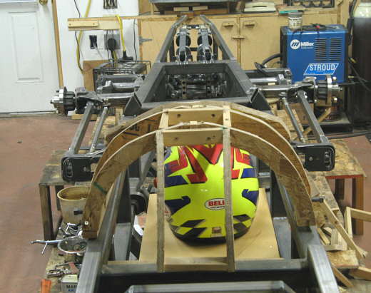
A view from just behind the cockpit looking forward...............................
................... .
.
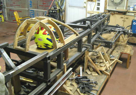
..............................and a side view from about the same point.
..............................................................Next Page