...Return To Mine & Other Bonneville Car Construction Pages
.Previous Page...............B'ville Car Index Page.........................Next Page
...................-- Spring Bucket Frame Connection --
................... .
.
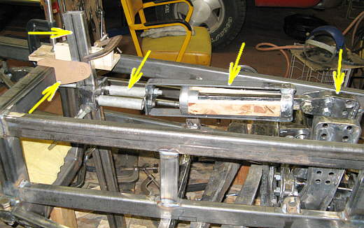
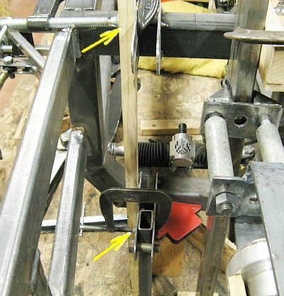
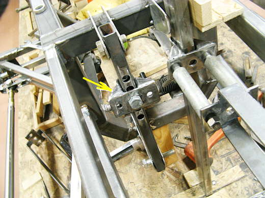
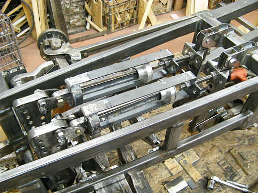
To finish off the front springs a means to connect the spring bucket to the frame had to be built. To summarize the right arrow points to the lever arm that moves to the left and right under axle travel. The second arrow from the right points to the spring bucket. The wood represents the spring. Under axle travel the lever arm pulls on the center section that is attached to the left end of the spring. The outer part of the cage is pulled to the left and compresses the spring and pulls the car to ride height. The third arrow from the right points to two pipes that are just locators at this stage and won't be in there when this is done. The top left arrow points to a temporary 1 X 2 piece of tubing that is positioned to hold the left end of the spring bucket assembly. The arrow below it points to a cardboard template I made for the first bracket that will be made.
................... .
.
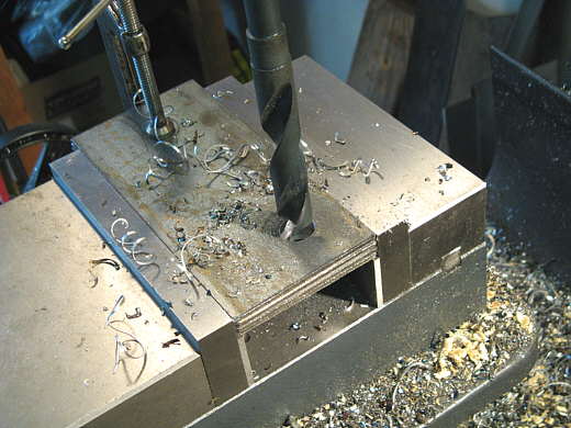
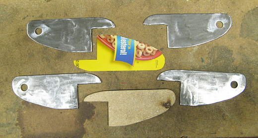
Four pieces of strap were cut the length of the template in the first picture and a 5/8 inch hole was drilled through all of them.
................... .
.
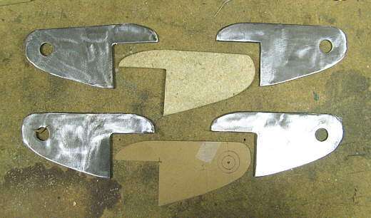
Using the template another template was quickly cut out of 3/8 inch particle board with a saber saw. That template was used to cut the final shape of the bracket with the plasma cutter and they were then all ground to the same shape at once with a bolt holding all of them together.
................... .
.
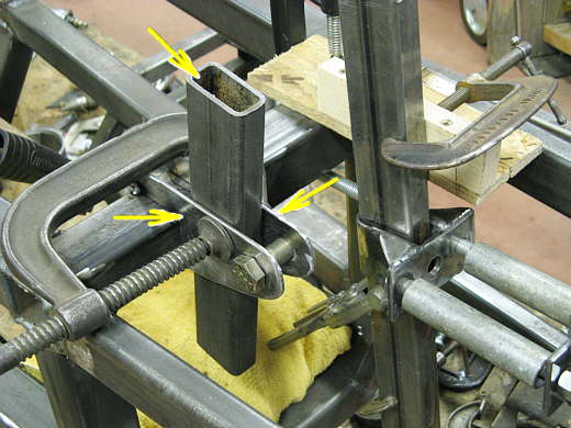
One of the brackets was tacked to the frame (lower left arrow). Then a piece of tubing (top arrow) was used along with a c-clamp to position and tack weld the other bracket. The assembly on the right allowed me to position all of this where I wanted it.
................... .
.
Next four bottom brackets where made the same way. I flipped the cardboard template over so that you could see that it was a cereal box. They seem to be just right for templates, so buy some Cherrios and help your heart at the same time.
................................... .
.
A straight piece of wood clamped to the top bracket and checked with a level allow the bottom bracket to be tacked into place.
................... .
.
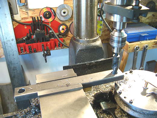
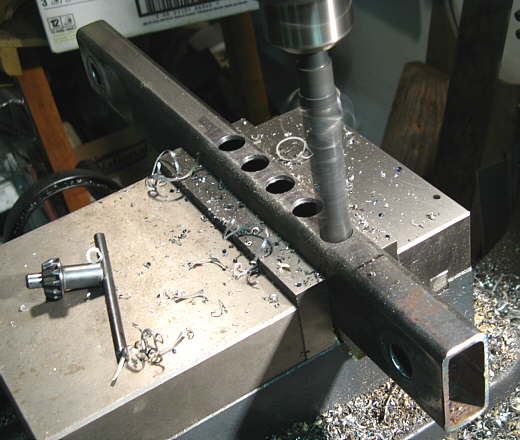
Now to make a piece to go between the brackets that will hold the inboard
end of the spring bucket.
Two 1 inch holes were drilled at the correct distance apart to match the hole centers of the brackets that were
put in place above.
................... .
.
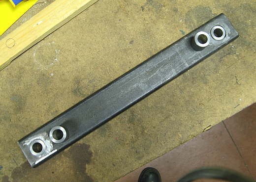
The lathe was used to make bushings with a 1 inch O.D. and a 5/8 inch I.D.. The other bushings laying on top will go in the other piece.
................... .
.
The bushings were Tig welded in place. I'm starting to really love the Tig I got.
................... .
.
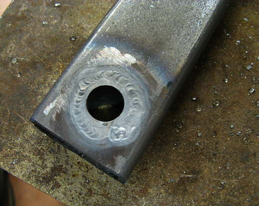
Next 5 holes were drilled through the tubing. These will allow the spring bucket assembly to move up and down to correspond to the 5 different settings that the spring can be moved to on the lever arm for suspension adjustment .
................... .
.
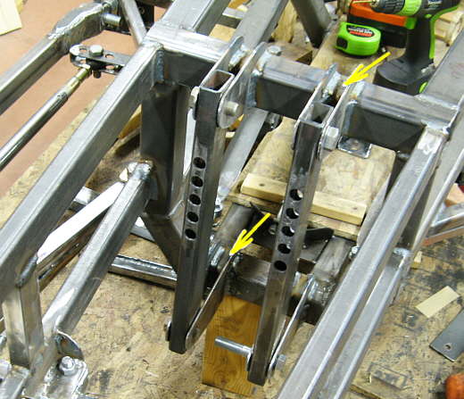
Here the left support is all tacked in place and you can see the piece (arrow) that slides up and down on it. I wanted the support to be removable in case I needed to change or replace the piece that slides up and down for any reason.
................... .
.
Here both supports are in place and the brackets have been welded in. The arrows point to areas where I will weld some other strap in to box these brackets in.
................... .
.
More or less finished with the spring assemblies for the front suspension. Here the whole assembly is located in the top most position on the lever arms. This would be the stiffest position as the springs would have the most leverage on the other end of the lever arms that ride on the axles.
On to finishing the shock supports that will locate the shocks to the frame.
..............................................................Next Page