...Return To Mine & Other Bonneville Car Construction Pages
.Previous Page...............B'ville Car Index Page.........................Next Page
.-- Middle Lever Arm's Pillow Block Support --
................... .
.
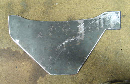
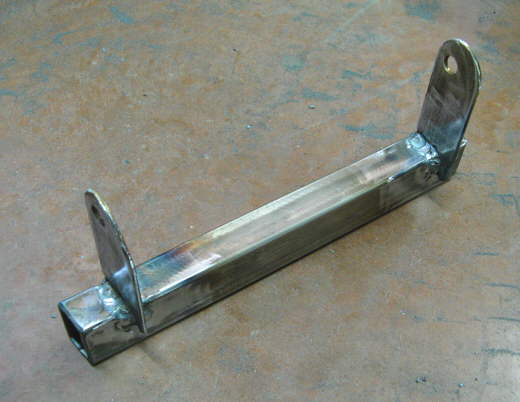
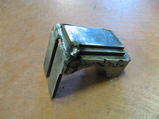
On this page the support for the two pillow blocks that the inner ends of the lever arm ride in will be built. I started by making a cardboard pattern and then used that to cut the above piece out of 1/8 inch by 6 inch strap. It was.................
................... .
.
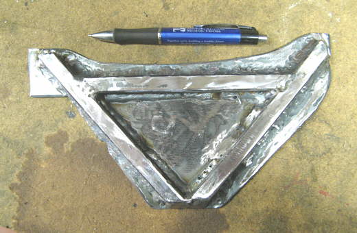
........................reinforced by welding some 1 inch by 1 inch thin wall square tubing to it..
................... .
.
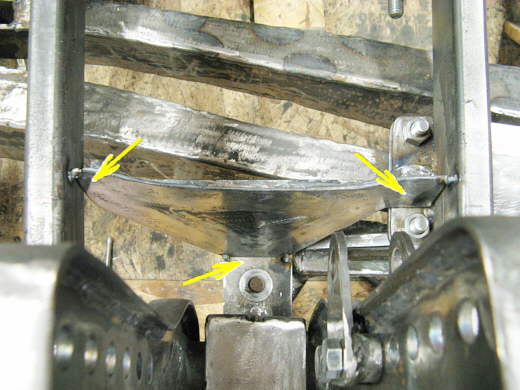
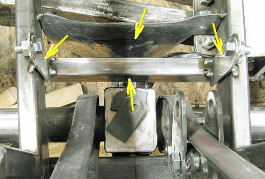
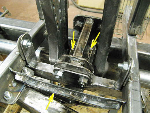
It was then positioned between the bottom frame rails (two upper arrows) and tacked to the piece if strap that the pillow blocks sit on (bottom arrow). It will stiffen the frame in this area. Locate and help support the strap at the bottom (bottom arrow) and it will reinforce the mount tab (top right arrow) that works with the right axle locator assembly. Later it will be welded completely in.
................... .
.
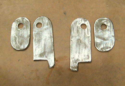
Four tabs were then made from 3/16 inch thick strap. Two of them.........................
................... .
.
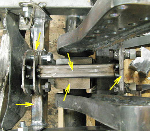
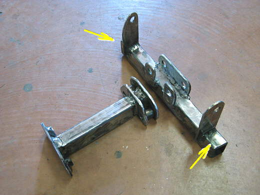
..............went on the left side frame rail and the left end of a piece of 1 X 1 1/2 .120 wall rectangular tubing (left arrow). The other two went on the opposite side (right arrow). The rectangular tube is cut so that it rides to the outer edges of the lower frame rails and just below them. The tabs just position it and there are no forces transmitted through them. The top arrow points to the piece that was made at the beginning of this page.
................... .
.
The rectangular tube cross-member that was tacked together in the previous picture. The forces on this piece will pull it up against the bottom of the frame rails on both sides.
................... .
.
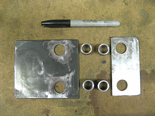
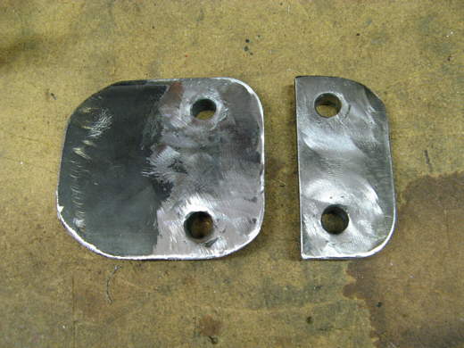
The next step was to make 2 bracket out of .120 thick (left one) and 3/16 thick (right one) strap. 4 bushings were made on the lathe with a 3/4 inch O.D. and a 1/2 inch I.D. The................
................... .
.
..........................bushings were placed inside the holes and welded........................
................... .
.
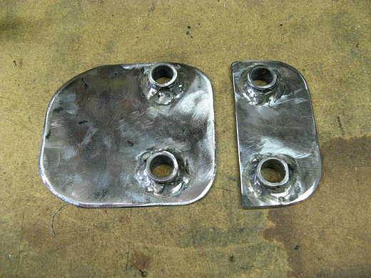
.............so that they were flush on one side. This will help to support the bolts that will attach these two plates and be in shear. The plates were rounded on the edges for appearance and the left one will be welded to the front cross-member. A rounded weld is a better deal than a straight up and down weld on the sides and a flat horizontal weld on the bottom as far as stress is concerned.
....................... .
.
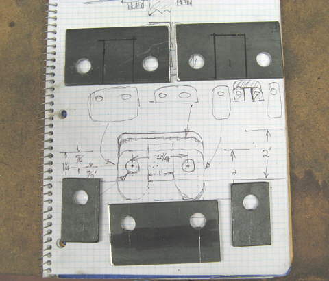
5 more pieces were also made from 3/16 inch strap after I drew a couple concept drawings.
................... .
.
Those pieces finished and ready to be welded on to a piece that will go above the pillow blocks.
................... .
.
A piece of 1 X 1.5 X .120 rectangular tubing (top middle arrow) is attached to the two previous cut pieces, one of which is welded to the front cross-member and the other tacked to the tubing. The tubing goes over the two pillow blocks middle arrow and over to the piece of tubing that rides under the frame rails (bottom left arrow). On the left are the 5 pieces from the previous picture that attach the two pieces of tubing to one another.
................... .
.
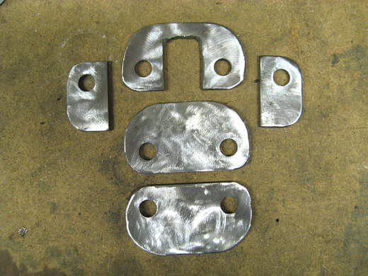
Here are the pieces that have been made to this point and that are ready for final welding.
................... .
.
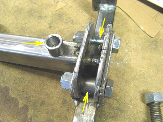
First though two bushings were made on the lathe that are inserted between the tabs (bottom arrow) so that when the assembly is bolted together the tabs won't be pulled in by the bolts. The left arrow points to the bushing that will be placed where the top arrow is.
................... .
.
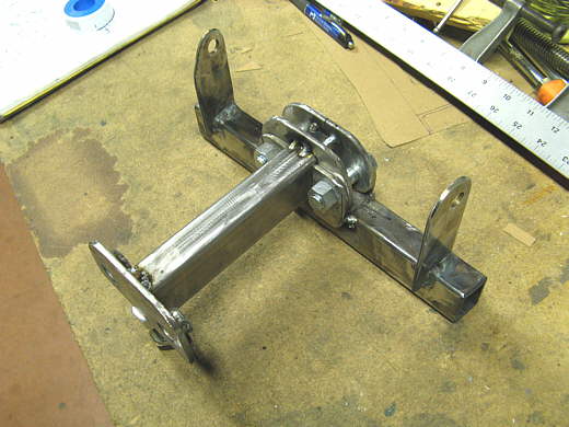
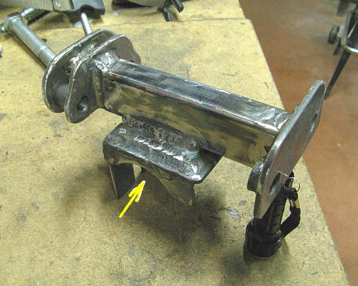
Here the two main pieces have been welded. All of the bolts will be in shear, double shear on the right side. The arrows point to the parts of the right tube assembly that will ride up against the bottom of the frame.
................... .
.
The two pieces bolted together. The reason they are not welded together is so that all of this can be removed from the car without having to remove any other parts. I've tried to keep the car so I can remove individual components without having to remove a number of items just to get to one. This was a difficult thing to accomplish in this instance and the piece that goes between the frame rails just barely comes out of the car without removing anything else.
................... .
.
At this point the support is almost done. The last hurdle is that the piece I made that captures the pillow blocks is 5/16 of an inch under the 1 X 1 1/2 inch rectangular tubing that goes over it. I solved this problem by .......................................
................... .
.
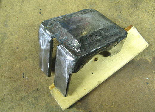
.....................welding a piece of 3/16 and 1/8 inch strap to the top of it.
................... .
.
I then welded that assembly to the bottom of the rectangular tubing. The arrow points to the cavity where the two pillow blocks reside.
................... .
.
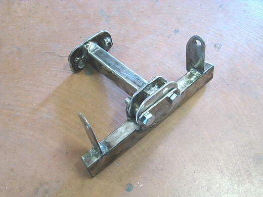
Everything in place. The bottom arrow points to the first piece made at the top of this page. The other two arrows point to the location of the pillow blocks for the inner ends of the two lever arms that are to the left and right of those arrows. The force of the pillow blocks will be upward on this assembly as the cars weight is pushing down on them. Now on to the front shock mounts and the front of the car's frame and suspension will be about done.
..............................................................Next Page