...Return To Mine & Other Bonneville Car Construction Pages
.Previous Page...............B'ville Car Index Page.........................Next Page
....................Shock Mts Part II and Odds and Ends
On this page I'll work a little more on the shock mounts, but I need to get some items taken care of by the front crossmember before it is to hard to work in that area, so I'll work in a couple different directions at once.
................... .
.
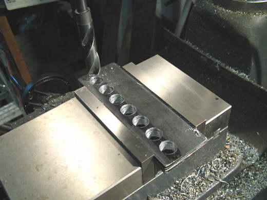
These brackets will hold the front of the shocks at the very front of the car. There are 4 plates here that seven 3/4 inch holes were drilled in. I screwed up since the shocks will mount directly to these pieces and there are only 6 possible shock mount locations, so..................
................... .
.
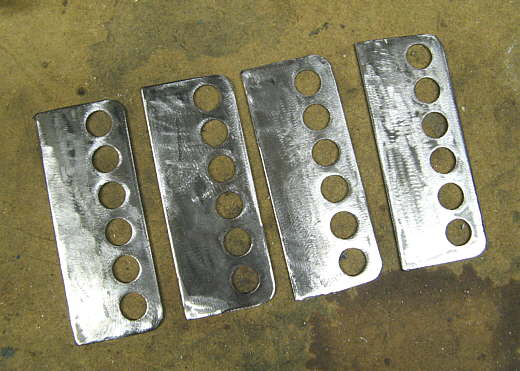
...................I cut one hole off the pieces to get back to the 6 holes I'll need. The holes are 3/4 inch so that a bushing can go in the holes. The bushing spreads the forces of the 1/2 inch shock bolt over a larger area and also captures the shock between the brackets and allows shocks with a different mount thickness to be used if needed.
................... .
.
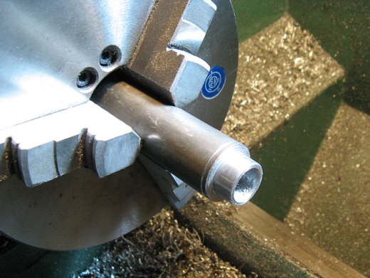
To make the bushings a piece of 1 inch cold rolled steel bar was drilled up the center for a 1/2 inch bore that the 1/2 inch bolt that will mount the shock will go through. I turned it down to 3/4 inch for a distance of about 3/8 inch. This 3/4 inch diameter will go through the bracket holes in the brackets above on this page.
...................
The rod was then cut so that there would be a shoulder that is a little over 1/8 inch at this point.
...................
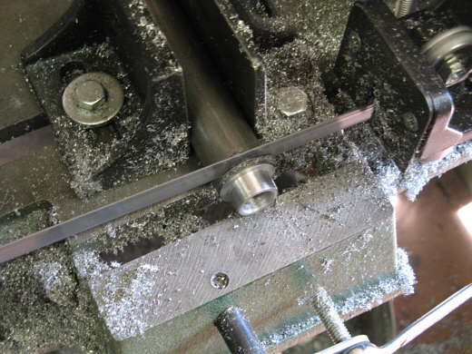
The shoulder was cut square to the bore and to a .120 thickness.
...................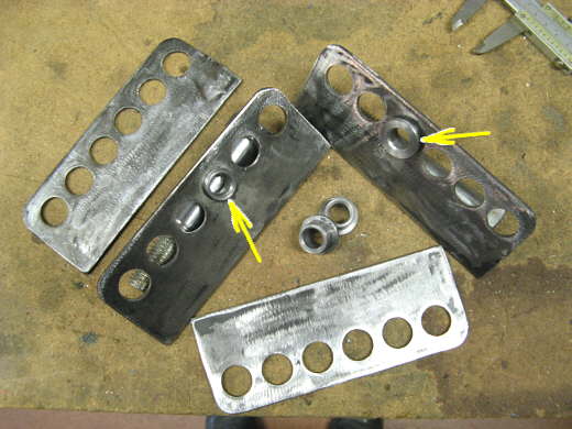
The 4 brackets and 4 bushings that will be used. The bushings will be inserted so that the shoulder is on the inside of the bracket then the shock will go between them and then a bolt will go all the way through. The bushings will capture the shock when the bolt is tightened and the shoulders will limit side to side travel. I stopped with the front shock mounts at this time to work around the front crossmember.
................... .
.
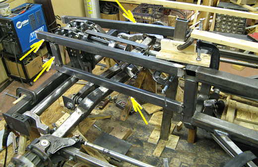
I extended the frame out to just in front of the crossmember with 4 horizontal members (3 of the arrows) and two uprights above the crossmember (bottom arrow on the left).
................... .
.
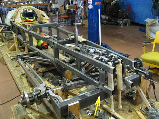
These new members will later get some diagonals for bracing and will be braced to the cage area of the main frame and also braced to the front crossmember (arrow). When I'm done with the work by the crossmember they will be extended to the very front of the car to hold the other end of the shocks that are laying up and down in the picture. The shocks will end up parallel to the ground at that point.
................... .
.
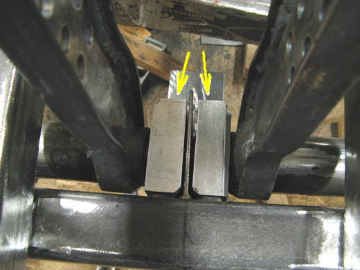
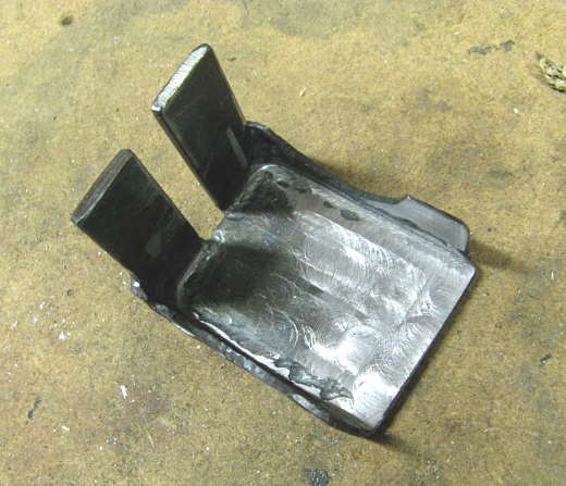
Earlier the the inner pillow blocks for the lever arms had been left sitting on a piece of strap. They need braced from above as that is where the force from them will be directed.
................... .
.
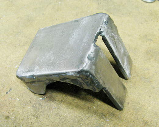
Some varies pieces of strap were welded up to make a piece that will capture them..........
................... .
.
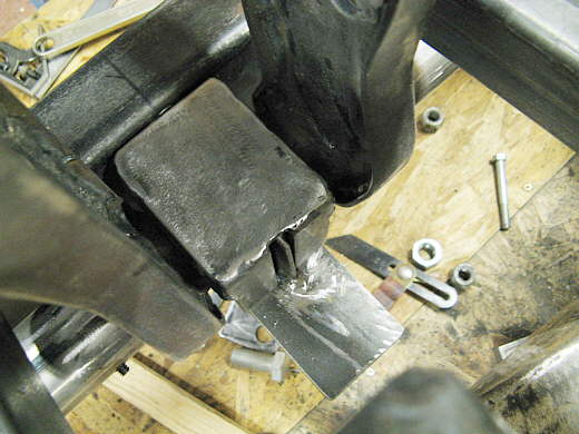
..............and then these piece in turn will be held in place and captured by a removable section of the frame that will tie into the crossmember and the side frame rails that were put in place further up the page.
................... .
.
The previous made piece in position and ready for the final support, but before I can do that I need to locate the inside end of the right front axle and that will happen on the next page.
..............................................................Next Page