...Return To Mine & Other Bonneville Car Construction Pages
.Previous Page...............B'ville Car Index Page.........................Next Page
........................................Front Shock Mounts Part I
................... .
.
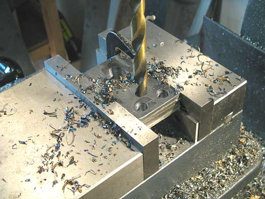
I needed 4 plates with 3 holes in them to mount the shocks to the lever arm. Here I'm drilling the 3 holes, one for the shock and two for mounting to the lever arm.
................... .
.
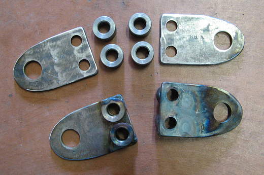
After the plates were cut with the plasma cutter and ground to the same shape. I had made the stand-off bushings earlier and here I've tacked them to the bottom two plates.
................... .
.
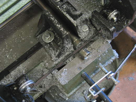
Next some 3/4 inch stock was cut about .600 inches long after I had drilled a 1/2 inch hole up the center of it in the lathe.
...................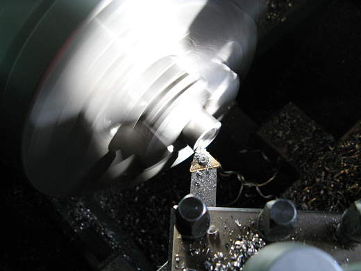
The piece was finished to .560 inches long and chamfered around the outside and beveled on the inside.
...................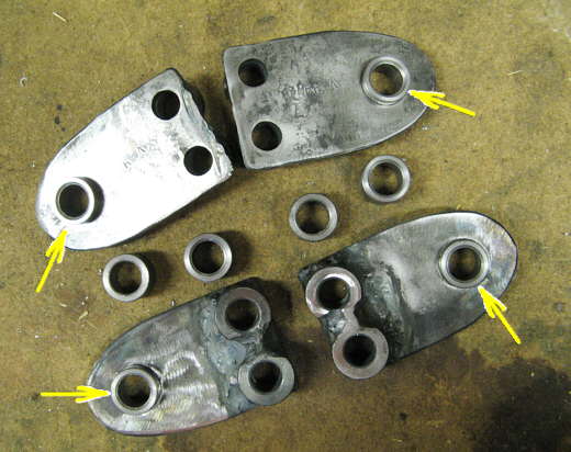
These pieces fit inside the 3/4 inch holes on the plates. One goes about half what through and is welded to the plate (I'll do that later when I get the shocks). The other floats in and out for different shock widths. When the shock bolt is tightened the shock will move towards the welded side and the floating bushing will draw up tight on the other side of the shock. I modeled these after commercial shock mounts I had bought from Speedway Motors and used on the back.
...................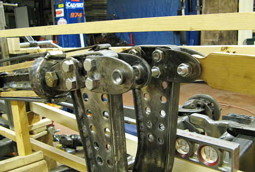
Here the mounts are located at the top of the lever arm with a dummy shock in the one to the right. I also moved the springs to the top so I could check clearance while I start the front frame members that will tie all of this into the car from the driver's compartment rearward.
................... .
.
The same view further away. I have the lever arms located about 1/2 way through their travel range so that I get all the mount angles for the springs and shocks setup mid travel.
................... .
.
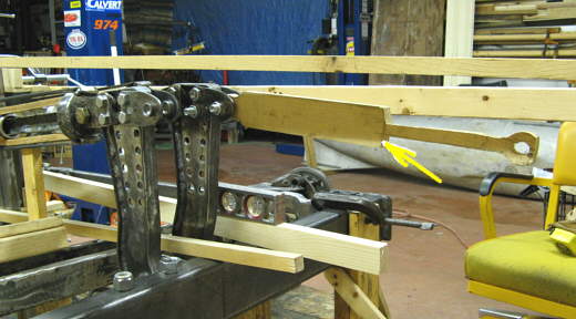
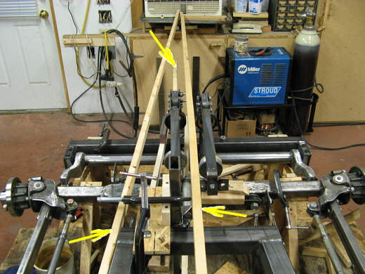
Here I'm trying to visualize where the frame members can go and still clear things and not trap components where they can't be removed. and yet keep the frontal area as small as possible at this part of the car. The top right arrow points to the wood member that represents the top of the body. The middle left arrow will be the top left side frame member and the bottom left arrow points to what will be the bottom left side frame member.
................... .
.
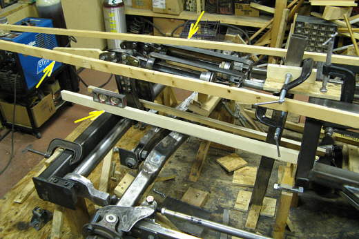
This top view shows how the left side frame members (bottom left arrow) will converge on the center line of the car (bottom right arrow) and pass the far end of the shock (top arrow). The nose won't be pointed like this. Just in front of the shock it will be rounded.
..............................................................Next Page