...Return To Mine & Other Bonneville Car Construction Pages
.Previous Page...............B'ville Car Index Page.........................Next Page
.............................................Spring Mounts Part III
................... .
.
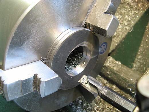
On the last page we attached one end of the front spring to the lever arm. Next is to attach the other end to the frame in such a way that it can be pulled on. This will compress the spring and raise the car to ride height. I needed to make a bucket to hold the end of the spring. I started by cutting some 3/16 inch X 3 strap into two 3 inch long pieces. I drilled hole in the middle and double nutted them to a 3/4 inch bolt with the head cut off. With this in the lathe I turned them slow and marked a circle on them with a magic marker as I've done in the past. I cut them to rough shape with the plasma cutter then turned them into 3 inch disks in the lathe. Next I held them by the outsides in the 3 jaw chuck and bored the insides to 1.40 inches so that the rod we made on the last page could go through them.
................... .
.
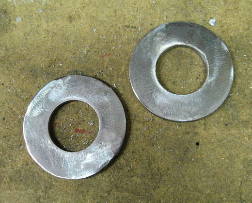
One for each spring. Next a .........................
................... .
.
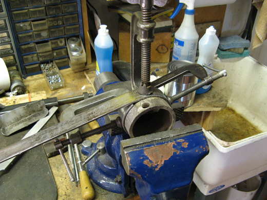
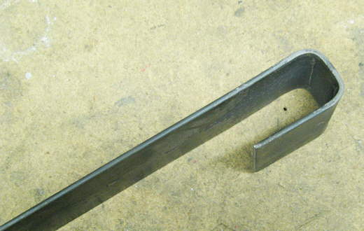
........... piece of strap was wrapped around a piece of 3 inch pipe and cut off and.............
...................
.............. welded to make a hoop. This.........................
...................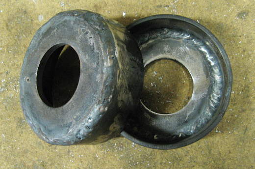
.............. was welded to the disk on the inside and outside to make a bucket to capture the end of the spring. On the last page when I first used the TIG I wasn't real happy with the results. My friend Rex Shimmer e-mailed me and told me that if I'm welding hot rolled steel that I should lightly grind the black scale off of the outside before welding. I did that on these and the welding went much better. Thanks Rex. These were shiny before welding and discolored some from the heat. Maybe I'm still welding too hot.
...................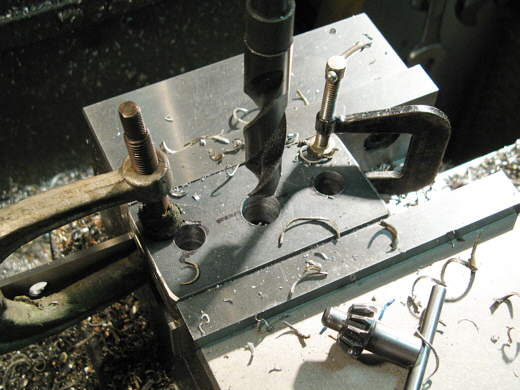
Next I needed to make some pieces that will attach to the frame and to the spring bucket. Two for each spring. Here I'm drilling 3 holes through 4 pieces at the same time.
................... .
.
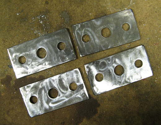
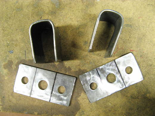
Here are the four pieces with the black off of them ready to weld. Hold on and this will make more sense in a minute.
................... .
.
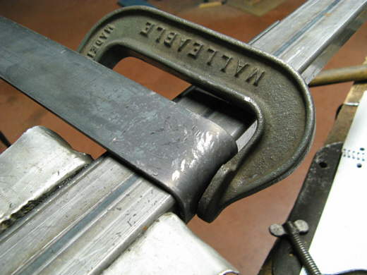
The spring mount on the frame side will slide up and down a piece of 1 X 2 rectangular tubing. To make the piece that will slide on it a piece of strap was bent around ...........................
................... .
.
............... a piece of the rectangular tubing into a "U" shape and cut off with equal legs.
...................
These will be welded on to two of the pieces with the holes in them and will be the piece that will slide up and down on the frame according to which sets of holes I use on the lever arms. This way the pull on the springs will always be at the same angle.
...................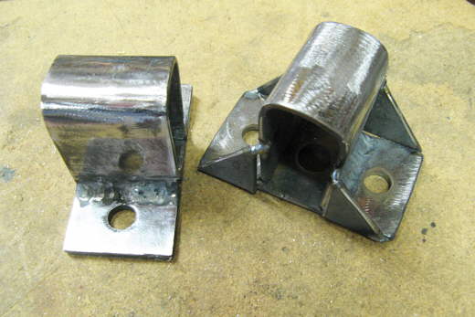
Welded together with gussets tacked onto one.
...................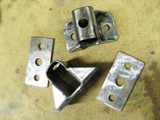
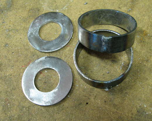
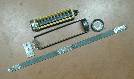
The finished sliding pieces along with the pieces that will pull on the spring.
................... .
.
At the top is the that was made on the last page that pulls on one end of the spring. Next down in the picture is one of the new pieces that will pull on the other end of the spring and below and beside it are the pieces to make the other one.
................... .
.
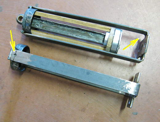
In the assembly at the top you can see the bushing that will attach to the lever arm. The plywood represents the spring. I'm waiting on some welding rod, so didn't complete the welding on the new pieces. The arrow on the left points to a hole that will be plug welded along with the other welds that will attach the strap to the bucket. The arrow on the right points to an area that will receive some gussets later to improve the strength in that area.
................... .
.
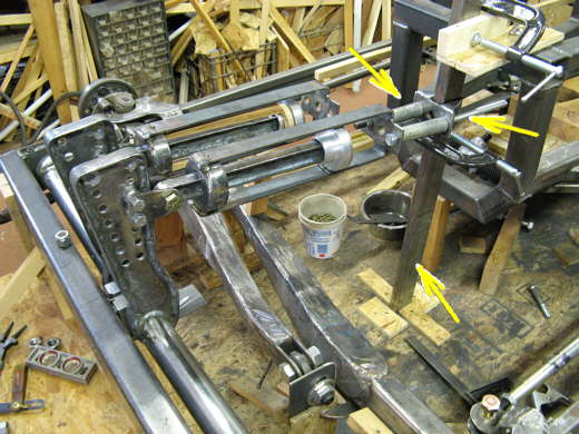
Here the spring assemblies are mocked into place for the time being. The lower right arrow points to the 1 X 2 rectangular tubing that will attach to the frame and has the sliding spring bracket on it (top right arrow). The top left arrow points to some temporary spacers. They will be replaced with bolts that will pull the spring towards the frame. Remember there were 3 holes in the brackets. The middle will be for a 5/8 inch "jack" type rod that will pull on the spring and compress it and raise the car to ride height. Once there two 1/2 inch grade 8 bolts of the required length will be put into the outer holes and will hold the bracket in position. If this doesn't work there is going to be a lot of rebuilding.
..............................................................Next Page