...Return To Mine & Other Bonneville Car Construction Pages
.Previous Page...............B'ville Car Index Page.........................Next Page
................................................Spring Mounts Part II
................... .
.
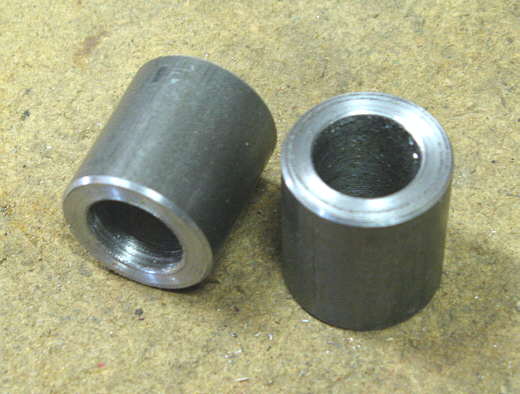
The spring mounts for the front will work on the same principal as what I did at the rear of the car. First I'll make a piece that will ride in the middle of the spring and will attach one end of the spring to the lever arm. The end furthermost from the lever arm itself. I started by making these bushing housings from 1 inch cold rolled steel. I cut the pieces a little long and machined them to length (1.070 inches) in the lathe and drilled a 5/8 inch hole in them. Later down the page the hole will be bored out to 3/4 inch. I wanted the hole undersized for now as I'll be welding on these and that will distort the hole.
................... .
.
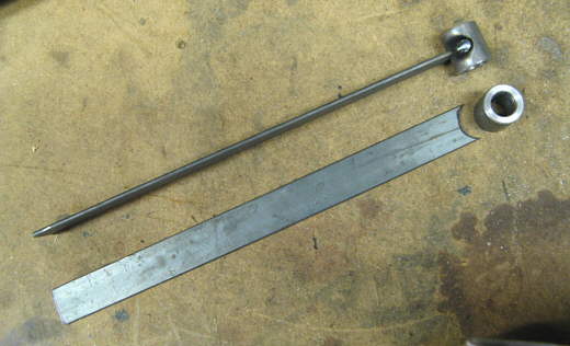
Two pieces of .120 X 1 inch strap were cut to about 12 inches long and trimmed on the end to fit the bushing housing.
................... .
.
Here these pieces have been welded together.
...................
A piece of .120 X 3/4 inch strap was then wrapped around the piece above and this makes the assembly resemble a piece of "I" beam.
...................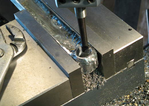
Now the end was bored out for a 3/4 inch bushing that will allow a 5/8 inch bolt to be used through it.
...................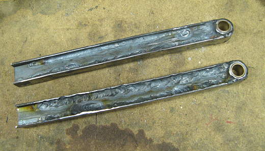
The two pieces with the bushings installed. These pieces will go through the spring and attach to the brackets that were made on the last page for the lever arm. Next I have to make a piece for the left ends of these that will hold the spring on one end.
................... .
.
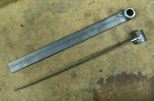
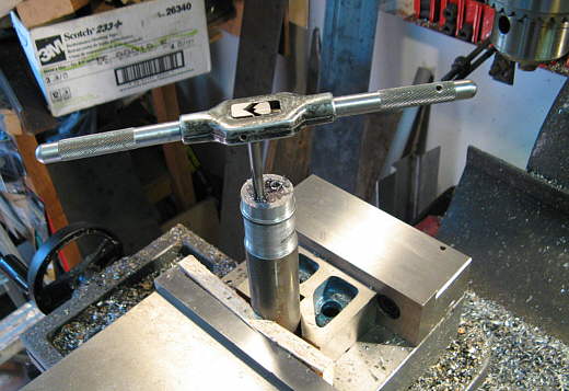
I took a piece of scrap round bar I had and drilled two holes 1/2 inch apart and 1/4 inch on both sides of the center. The holes were tapped for 1/4 inch bolts.
................... .
.
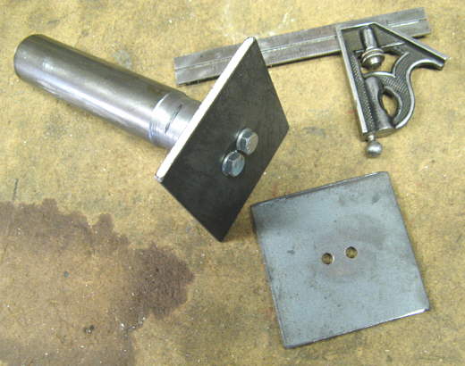
Two pieces of 3/16 X 3" X 3" strap were cut and two holes were drilled in the center so the pieces could be bolted to the rod.
................... .
.
I put the rod and attached strap in the lathe and spun it and marked a 3 inch circle with a magic marker. I cut the circle out just outside the marked circle with the plasma cutter and ground it kind of smooth. Then I put it back in the lathe and turned the final circle.
...................
I marked the center and placed the "I" beam like part made above on the circle and traced around it with the magic marker.
...................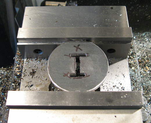
Then the piece was put in the vice on the mill and I slotted the piece with an end mill.
...................
The I-beam was put in and slightly through the slot and welded on both sides with the TIG. Now I have a piece that will hold the end of the spring and attach to the lever arm, but there needs to be one final piece made to center the spring on this assembly.
................... .
.
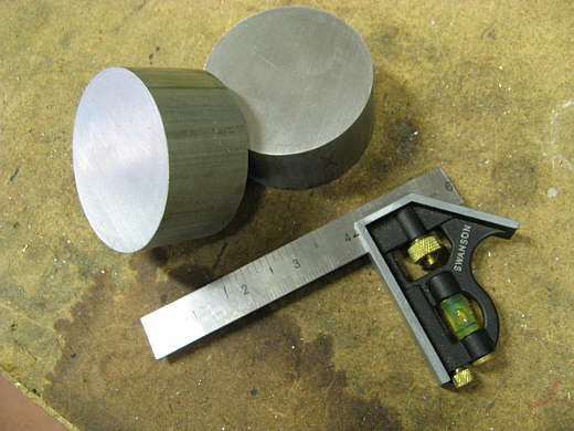
I had some aluminum round stock I got from a salvage yard that was 3 inches in dia.. I cut it to the length I wanted with the band saw..................
................... .
.
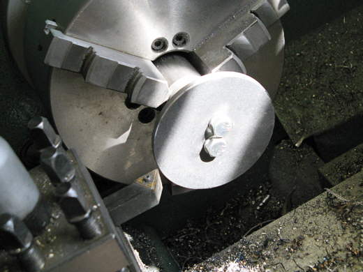
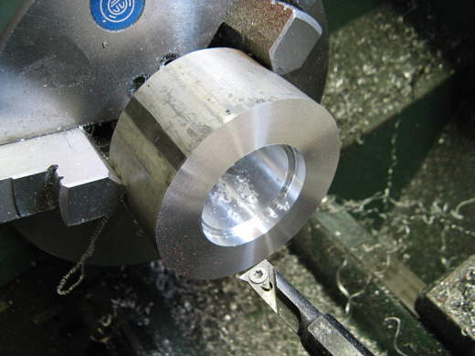
.........and then put one piece at a time in the 3 jaw chuck on the lathe. I drilled the center out to 1 inch with the largest bit I had and then bored the inside out to 1.450 inches followed by the other recessed cut that is for clearance purposes.
................... .
.
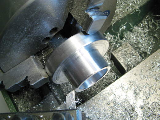
Turning the piece around the other end was machined down to 1.800 inches which will fit inside of the 1.875 ID springs I'll use.
...................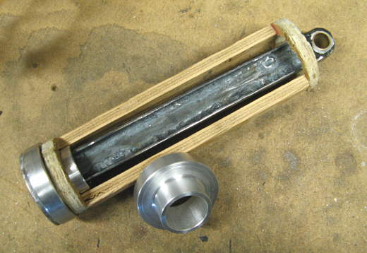
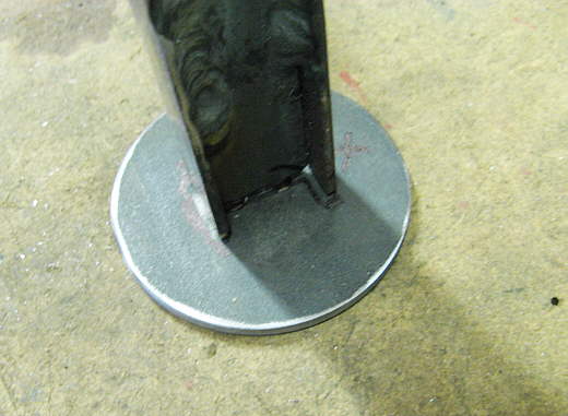
The two finished aluminum locators. The plywood piece represents the 10 inch long spring. You can see how the aluminum piece slides over the I-beam and locates one end of the spring.
...................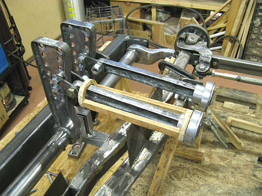
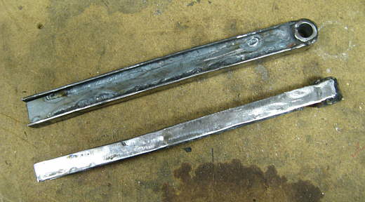
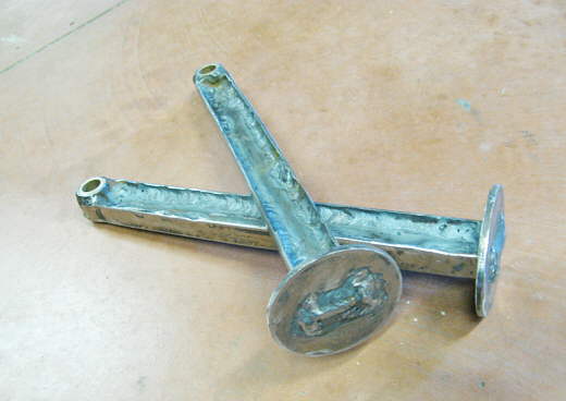
The two pieces attached to the lever arm. Next will come the two pieces that will capture the other end of the springs and that will be attached to the frame. They will be adjustable to pull on the spring and pull the car up to ride height.
..............................................................Next Page