...Return To Mine & Other Bonneville Car Construction Pages
.Previous Page...............B'ville Car Index Page.........................Next Page
.................Front Suspension Lever Arms -- Part IV
................... .
.
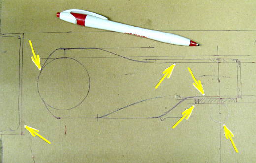
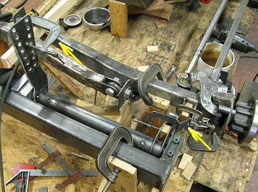
Now to make the lever on the other end of the lever arm tube that will react to axle movement. Here again I made a full size to scale drawing. The bottom arrow on the right points to the bolt this lever will sit on. The arrow above and to the left points to a plastic wear pad that will fit on the bottom of the lever arm. The two top right arrows point to 1/8 inch strap that will wrap around the lever arm and the two left arrows point to the 2 X 4 rectangular crossmember and the 2 inch dia. lever arm tube.
................... .
.
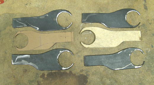
Like on pieces in the past I took the paper drawing in the picture above and made a particle board pattern and then cut the pieces out with a plasma cutter using the pattern. Instead of drilling these holes with a hole saw I cut them with the plasma cutter and cleaned them up with a die grinder. That went pretty good except I hate the slivers from cutting with a die grinder. I vacuum right away, but still seem to get them in my hands later.
................... .
.
Here I'm grinding them so that they are all the same shape and size.
....................... ....................
Next I put the bends in the pieces since the bolt they will ride on is offset from the end of the lever arm tube.
..................
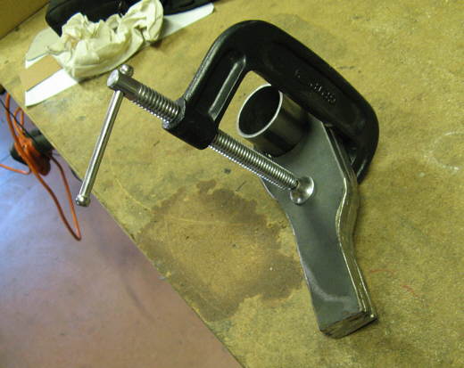
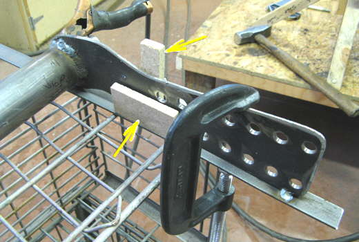
I positioned the lever arm with the inboard lever where I wanted it and clamped it into place (left arrow). I put wood spacers between the two pieces that make up the outer lever arm (right arrow). I also moved the axle up about 3/4 inch to represent mid travel on the suspension and then welded the new pieces I had made to the outboard side (right arrow) of the lever arm tube.
.................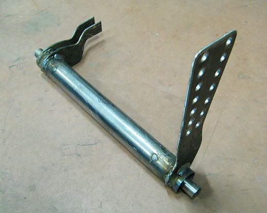
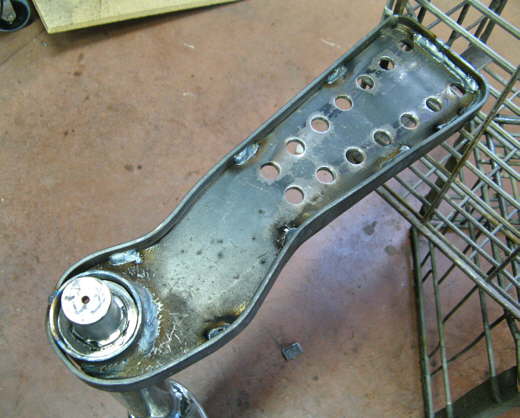
Here is one lever arm assembly after the last step.
..................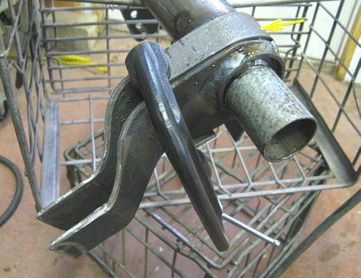
Next a piece of strap was clamped into position that went from the bottom of the lever arm, around the lever arm tube and to the top side of the lever arm. this was then tacked into place. During this I put a short piece of galvanized pipe over the end of the tube to protect the bearing surface from splatter.
.................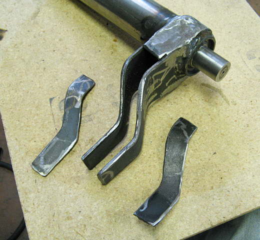
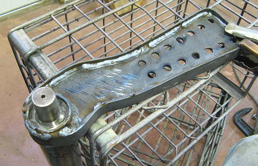
Here you see the last piece welded into place and the pieces I made to go on the top and bottom. There was also another short piece that was welded to the end.
.................
After all the pieces were welded on I cut a slot in the bottom of the lever for a tab that is on the wear pad.
......................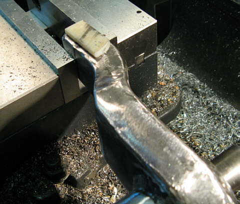
The wear pad has been pressed into the slot in this picture. Speedway and others sell these to work with cars that have torsion bar suspensions and a lever arm that rides on the axle itself. I didn't go that way as I didn't know how to pick a torsion bar for my setup and since having it on top of the axle would increase the overall height (frontal area).
.......................
Well almost done. One more step. I wanted to wrap a piece of strap all the way around the inner lever arms to tie them to the tube and to stiffen them up.
...................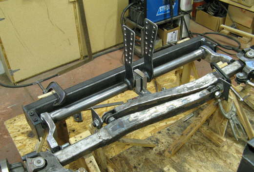
But first here is the way what has been accomplished so far looks in the car.
...................
I use 1/8 inch by 1 inch strap to wrap all the way around the arm. The arrows point to two pieces of particle board that helped me center the strap as I welded it. I bent it to conform with the arm as I worked around the arm and tacked it as I went.
...................
Here I have just finished wrapping the strap and tacking it to the arm.
...................
Finished welding the strap on both sides all the way around. Thank goodness for mig welders.
...................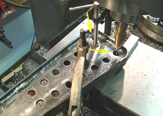
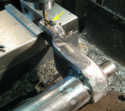
The top holes were close to the strap and I needed to clearance the weld in that area for the mounts I'll make next. I used the mill for that. Thank goodness for mills also!!
...................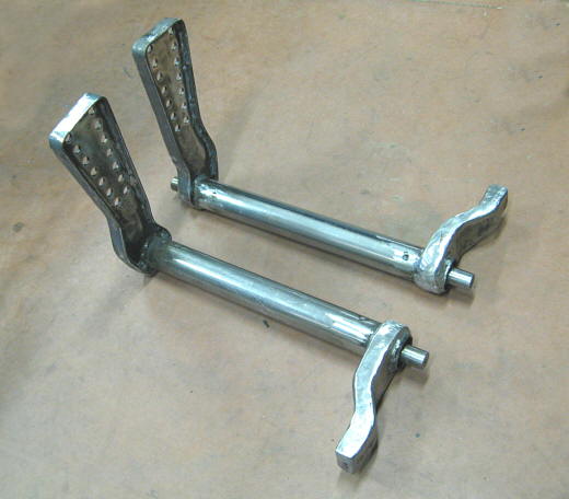
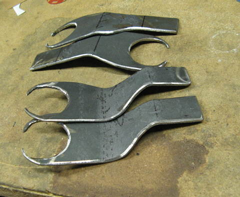
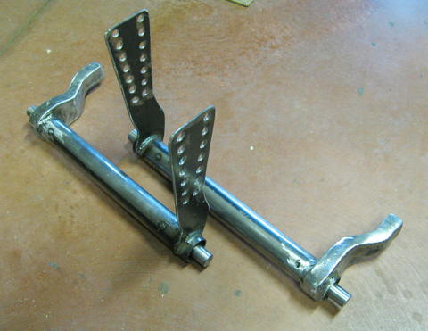
Finally the finished lever arms. They look pretty massive, but since they are
hollow they only weight 11 1/4 lbs each and they move with just the touch of a finger even with weight on them.
Hope all of this works. I like these a lot better than the ones I made for the back of the car and might go to
this design back there someday, but first let's get this thing finished and on the salt. I'll be very disappointed
if that doesn't happen in 2008.
..................................................................Next
Page