...Return To Mine & Other Bonneville Car Construction Pages
.Previous Page...............B'ville Car Index Page.........................Next Page
.................Front Suspension Lever Arms -- Part III
................... .
.
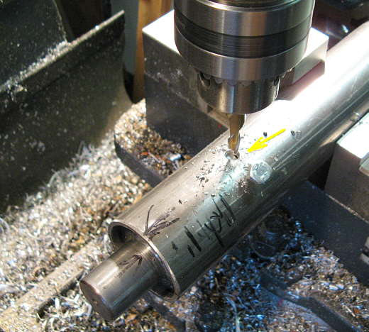
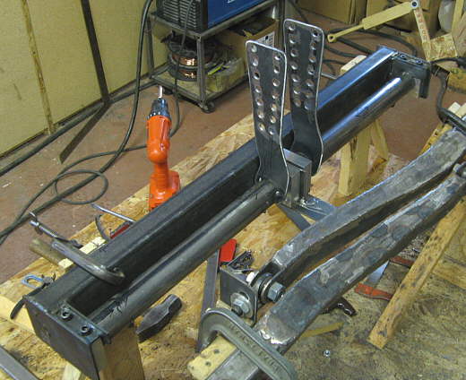
I milled in three holes into the lever tubes around their circumference so that I could plug weld the bearing shaft assemblies into the tubes.
................... .
.
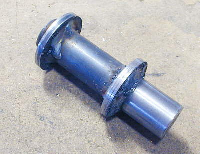
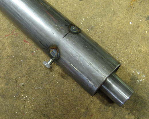
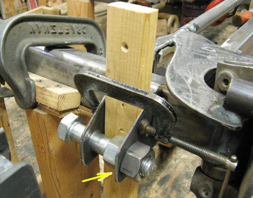
Here you can see 2 of the 3 holes that were plug welded. The bolt is in a threaded hole that held the bearing assembly in place during this procedure.
.................................. .
.
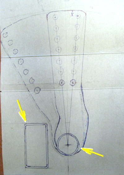
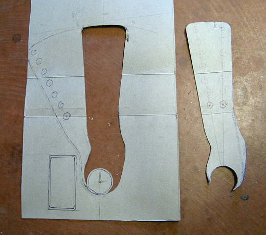
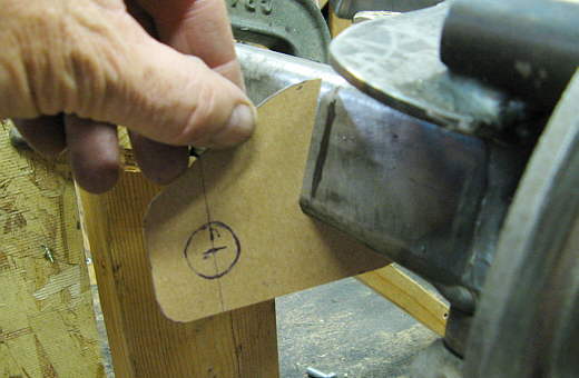
Next was the building of 2 lever arms for each tube. An outer one to ride on the axle and an inner one that would hook to the springs and shocks. I started with the inner one and drew a full size drawing of what I wanted on the back of a cereal box. The rectangular tube crossmember is the left arrow and the right arrow points to the lever tube. I needed to make this lever arm clear the crossmember during suspension movement. The set of holes going up the right side will be where the spring can be mounted and the holes up the left side is for the shock mounting. They will both have multiple mounting locations to vary the spring and/or shock rates.
.................... ....................
I cut my pattern out........
....................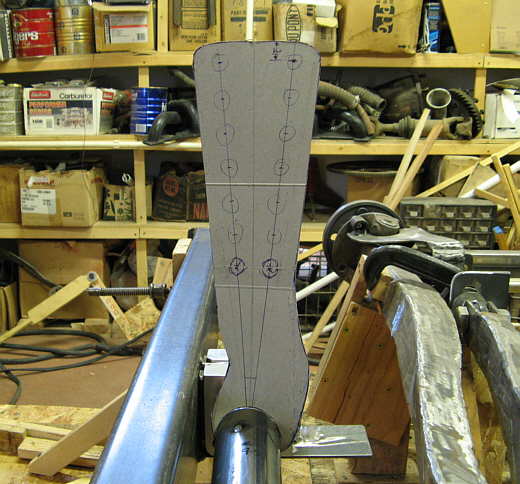
.............and attached it to the tube for a real world test. Happy with that I ...............
....................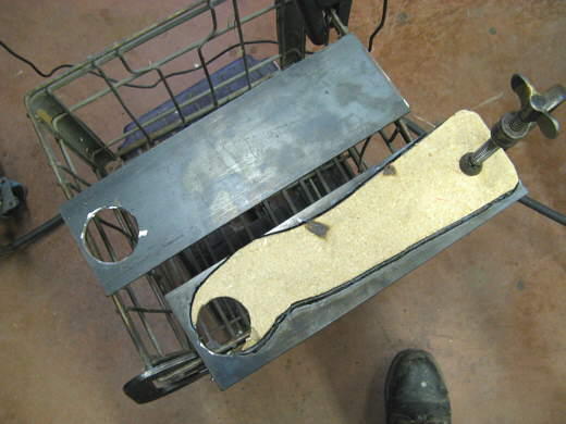
............... used the cardboard pattern to make one out of particle board. I took some strap and drilled a 2 inch hole in one end for the lever tube and laid the pattern on the strap and cut it out with the plasma cutter.
....................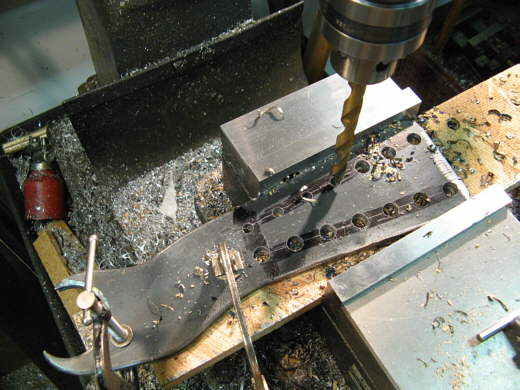
I clamped the two pieces together and used the hand grinder to make them the same. Then I clamped them to a piece of wood and drilled the holes going up both sides on one inch centers. The nice thing about using the table on the mill it is very easy to get consistent one inch centers time and again with the screw feeds.
....................
After the drilling operation I tack welded them onto the tube in the position I wanted them.
....................
I then moved on to making the mount on the axles for the other lever arm to ride on. First was another pattern first with cardboard and then from there to a particle board template.
...................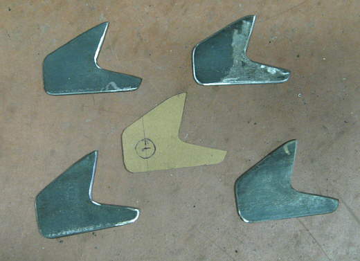
I used it to cut out 4 mounts with the plasma cutter and ground them to the final shape.
...................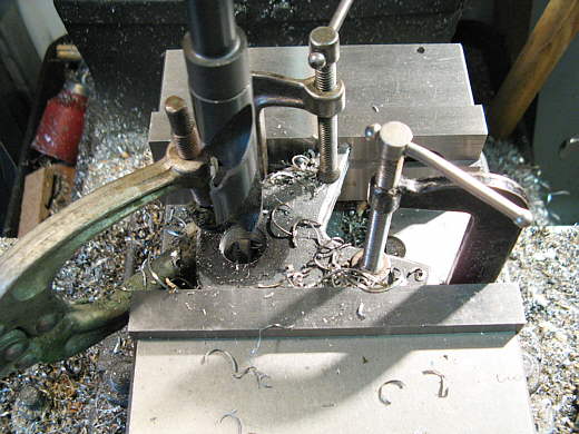
Here I'm drilling the 3/4 inch hole through all 4 of them at once.
...................
I tack welded the right one (arrow) on first. Then I put a 3/4 inch bolt through the other one and then double nut the bolt to the one that was welded on. This held the other one in the right location. The 1 X 2 piece of wood is spacing them 1 1/2 inches apart. With the left tab in place I tacked it.
...................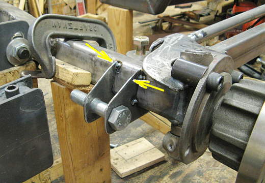
Here are the two tabs in place. Later I'll add strap to the outsides of them
(see arrows) that will tie them to the axle and make them much stronger. The outer lever arm will ride on the bolt
and the bolt will later be replaced with a grade 8. Now on to the inner lever arms.
..................................................................Next
Page