...Return To Mine & Other Bonneville Car Construction Pages
.Previous Page...............B'ville Car Index Page.........................Next Page
...................................Radius Rod End Brackets
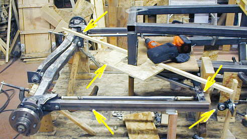
Next up for the front was to finish locating the front axles. One end of the axle is located by a heim joint on it's inboard end (top left arrow) much like a Ford twin I-beam setup. The spindle/hub end is located by a radius rod (bottom left arrow).
................... .
.
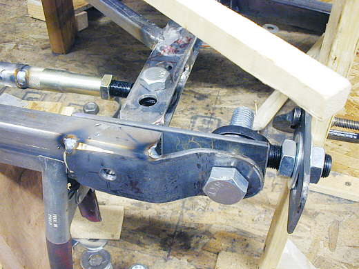
The right end of the radius rod will receive a bracket that will attach it to a heim joint (bottom right arrow) that later will be mounted to an outrigger coming off of the cage/frame. To minimize "bump steer" I wanted the tie rod mounting point to the steering bellcrank (top arrow on right side) to be on the "hinge" line of the front axle/radius arm. The front axle/radius arm will pivot on the two heim joints (one on the end of the axle and the other on the end of the radius arm). The location of the one on the axle was already fixed, but I needed to locate the location of the heim on the end of the radius arm. I used a piece of wood that has a "U" shaped piece of wafer board in the middle of it to jog around the front of the cage. I put one end of the piece of wood over the heim at the end of the axle and the other end over the end of the tie rod. Going further out on the piece of wood gave me the location for the heim joint. Hope this is clear.
................ .
.
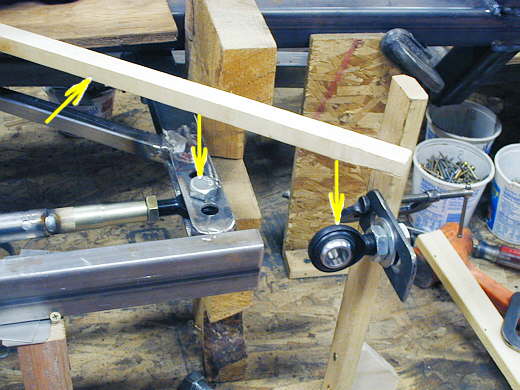
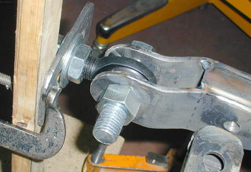
Here you can see how the piece of wood is directly above the bolt that holds the tie rod to the steering bellcrank. To the right of that you can see that I have positioned the heim directly below the piece of wood and behind the radius arm. Now I have to continue the radius arm to the heim joint. This will result in the tie rod attach point being located on a line between the two heim joints and will reduce bump steer.
.................................. ....................
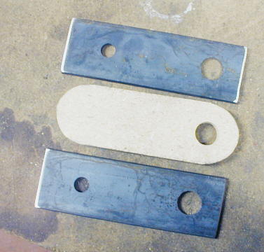
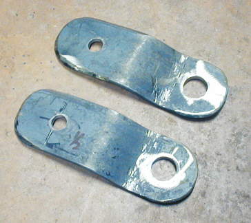
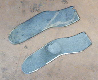
I cut 4 pieces of 3/16 X 2 inch strap (2 shown here) to use for the brackets. The small hole on the left side is for a future plug weld on the radius arm and the 3/4 inch hole is for the bolt that will go through the bracket and the heim joint. The 3/8 inch thick particle board pattern will be used to cut the ends with the plasma cutter.
.................. .
.
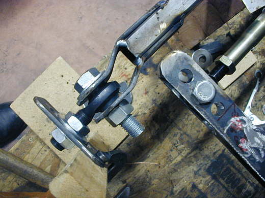
The bracket had to be bent to move the bolt head inside towards the center of the car for clearance on the body later that will be right along side of the radius arm. I clamped one piece of strap onto the inside of the radius arm and ran a bolt through the heim just to get the outer bracket bent and where I wanted it. At this point nothing is welded into position.
.....................................
After I liked the fit I bent a second one the same for the other side of the car. Next the plasma cutter and particle board pattern were used to round the ends. I wanted to round or cut the welded end at an angle so when I welded it to the radius arm I don't create a straight up and down stress point where the weld is on the radius rod. I had something fail once in that situation, so try and avoid it now if possible.
..................
Here one side of the bracket is tack welded into place.
.....................
The heim joint was moved over onto the first piece of the bracket and the inside piece was then bent to fit and clamped to the radius arm at one end and to the heim at the other.
...................
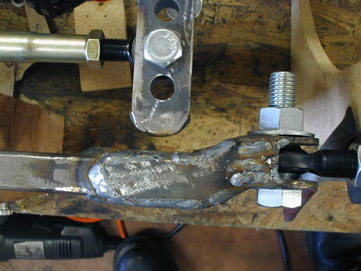
It was also tack welded into place. In this view from above you can see how if the body follows along the side of the radius arm it will now clear the bolt head for the heim bolt. The bracket that the threaded end of the heim is attached to will later be located to the frame/cage to locate the heim at this spot.
.........................................
Lastly two pieces of 1/8 inch strap were cut that will be welded to the top and bottom of the bracket that was made above.
...................
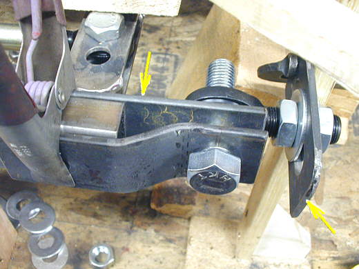
Here you can see the piece above welded into place. Note with the off-set the bolt head is now inside the outer plane of the radius rod and will clear the body.
..................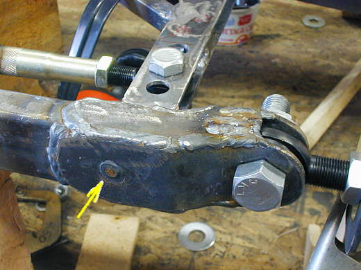
Here you can see where I also plugged the brackets (arrow). At this point the radius arm on the other side of the car is finished to the same degree.
..................................................................Next Page