...Return To Mine & Other Bonneville Car Construction Pages
.Previous Page...............B'ville Car Index Page.........................Next Page
............................................ Steering Arm Part I
.............. .
.
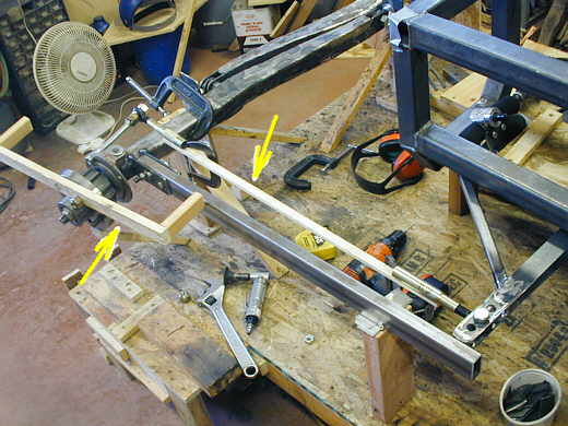
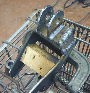
On this page I'll build a steering arm that will hook to the spindle and attach to the tie rod for the steering. I started with a piece of wood (top/right arrow) that acted like the tie rod and was attached to tubing and a heim joint at each end. I used a long bolt to the spindle to see how this would work. The piece of wood on the spindle (left arrow) represents the tire and shows how far the wheel can be turned to the left before the back side of the wheel/tire hits the radius tubing (the 1X2 rectangular tubing).
.............. .
.
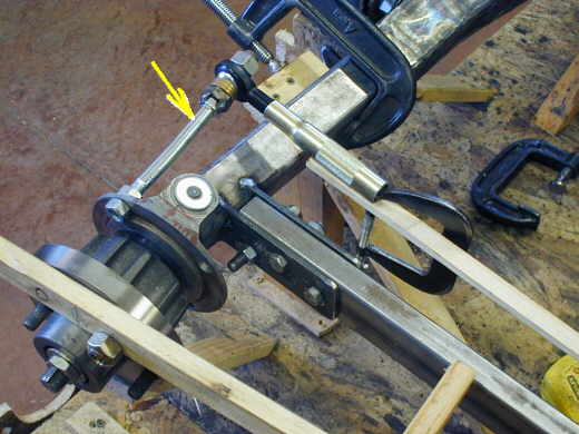
So what I needed to make was a steering arm that would replace the bolt (arrow). I use the bolt to see how long I needed it for leverage on the spindle/wheel/tire. I wanted to make something that hugged the axle and radius tubing so that the aero frontal area would be reduced as much as possible.
............. ....................
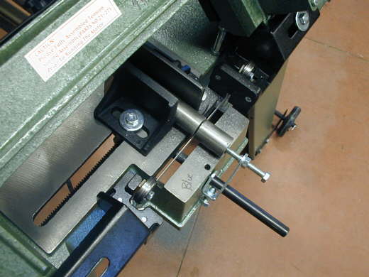
I started by cutting 4 pieces of 1 inch cold rolled rod with the band saw. I used the HF bandsaw I got on sale for about $160.00. This is not a real heavy duty bandsaw, but by buying some good bi-metal blades from ENCO I've been very satisfied with it.
.............. .
.
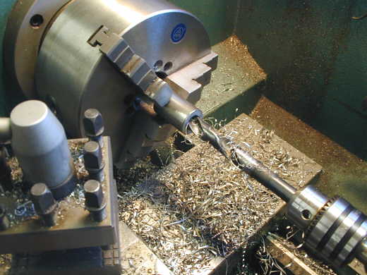
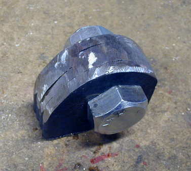
Next I bored all the way through the rod with a drill the right size to tap the hole for a 1/2 inch fine thread allen screw. Then I bored part way through with a larger bit, so there is a stepped hole in the rod.
...............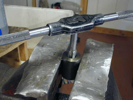
Here the rod is getting tapped.
.....................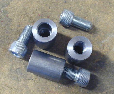
I ended up with 6 of these altogether, 3 for each spindle.
..............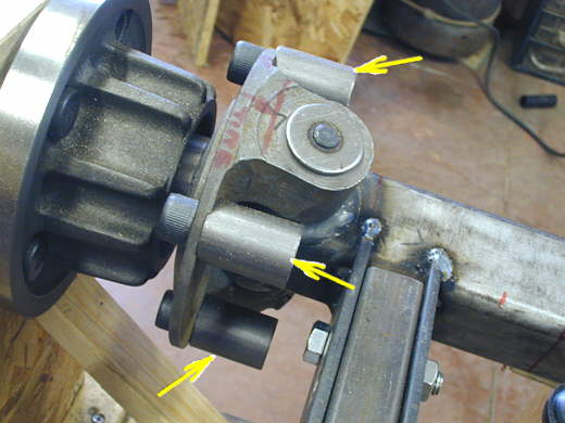
The arrows show where the 3 pieces are mounted to the spindle in holes that are there for this purpose.
...........................
The 3 pieces of rods will act as the attachment points for the rest of the steering arm to the spindle. I had some 3/16 X 4 inch strap, so I used a piece of paper 4 inches wide and starting marking and cutting it till I came up with this pattern.
.................................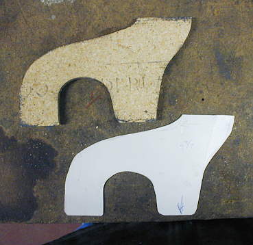
In a few minutes I had the pattern traced onto a piece of 3/8 inch particle board and cut out with my saber saw.
...........................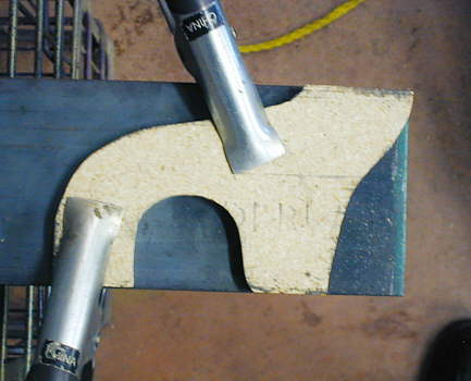
I clamped the pattern to the strap and using the plasma cutter quickly cut the piece out. From here on out the car will enter the AP era (after plasma cutter) vs. the BP era (before plasma cutter). I could of made this piece using the saber saw or the cutting torch, but it would have taken much longer. Making these simple wood templates and not burning them up and ending up with a piece that needs very little grinder work is amazing.
......................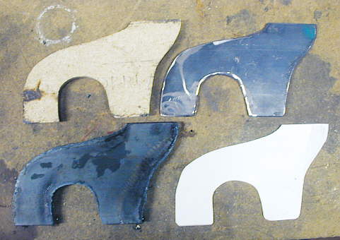
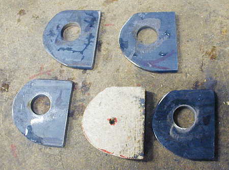
Here is the paper pattern, the particle board pattern, and the two metal pieces, one ground and the other with a little slag on it. I'm getting better with the speed to drag the plasma cutter since these and I'm ending up with even less slag and it is easy to knock right off. One of these is for one side of the car and the other for the other side.
.................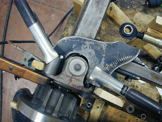
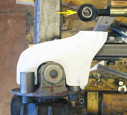
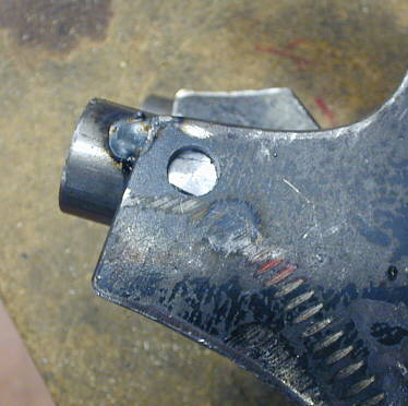
Next with the piece under one attachment boss and over the other I tacked it to the two round bosses. You can see the end of the tie rod in place at the upper right. That is where we are headed. The new piece was not quite level front to back, so I bent it slightly so it would be level in the area of the tie rod.
..................................
These are 4 tabs being made that will hold the tie rod in double shear to the steering arm. The bolt that is holding them together for final grinding to shape is a 5/8 inch bolt the same size that will be used on the tie rod.
..........................
Here you see the four tabs with the pattern I used to rough cut them to shape with the plasma cutter. I had drilled the hole before I cut them all to shape.
..................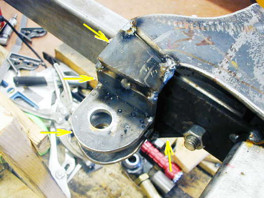
The first piece of the steering arm is coming into the picture from the top right. I had the tabs (bottom left arrow) bolted to the tie rod at final height (here the tie rod has been removed. I put a temporary piece of strap level and clamped to the bottom round boss on the spindle (bottom right arrow). Then I cut and rested a vertical piece (3/16 X 2) on the bottom piece and against the 2 tabs (middle left arrow) and tacked it to the tabs. With all of that in place I made a pattern and cut the piece (top arrow) to attach the vertical piece to the main part of the steering arm going to the spindle. There is an angle there that helps with clearance on the radius rod when the steering is turned.
..................
Finally I removed the bottom temporary piece and made a pattern and cut a bottom piece that went from the boss on the spindle over to the vertical piece the tabs are welded to.
....................................
I cut a piece of wood and clamped it into the assembly before I started my final welding. It helped with warpage, but I still had to tweak the piece a little when the welding was done to get the mounting bosses back lined up with the holes on the spindle.
....................................
For added strength I milled some 3/8 inch holes through the steering arms and into the bosses and then plug welded them shut.
.......................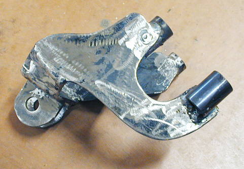
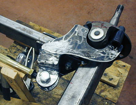
Here is the finished piece. I've considered..................
..............................
..........adding some bracing at the angles, but it seems very strong at this point and I have a lot of confidence in it just the way it is.
.............................
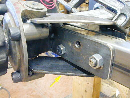
Here it is mounted up with the temporary tie rod in place. Seems to work...........
...................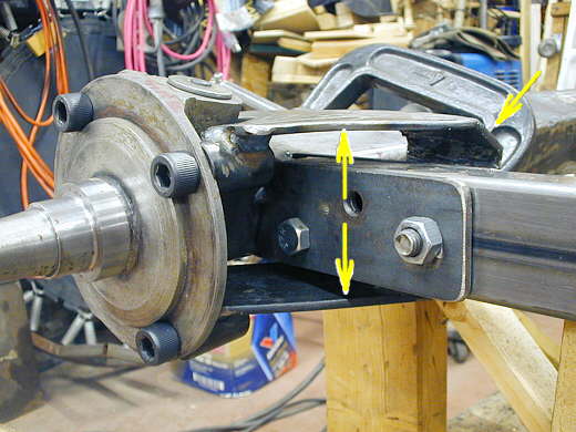
..........very well and the height is just 3 1/5 inches at the double arrows. At the right arrow you can see there is fair among of clearance between the arm and the top of the radius rod, but that decreases when the steering are turns due to the 18 degrees of castor. As the wheel is turned one way the arm goes down and when it is turned the other way from the neutral position it raises due to the castor angle.
...................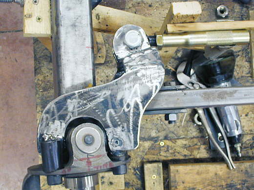
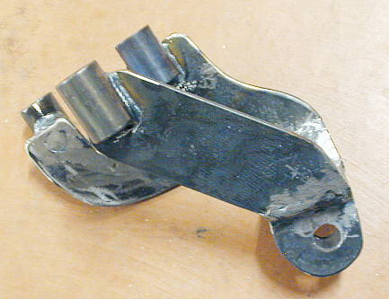
And from above. Now the trick is to make the other side a mirror image of
this side. I'm going to have to make a jig to do that so that the tie rod on the other side is in the same place
in relation to the spindle. It is good to be back working on the car again :-) .
..................................................................Next Page