...Return To Mine & Other Bonneville Car Construction Pages
.Previous Page...............B'ville Car Index Page.........................Next Page
....................-- Fuel Tank Part III & Fuel Lines --
.................
.................. .
.
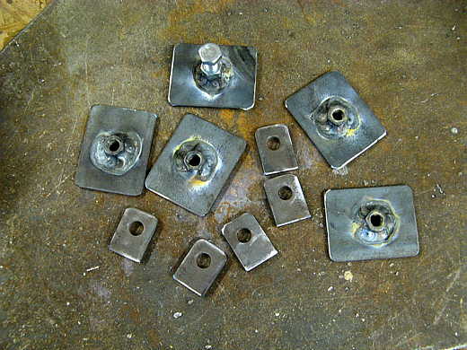
The fuel tank needed to be mounted in the car and I wanted to mount it on a little rubber, so thought some mounts that clamped the tank in the car would be a good deal. I made the pieces above. The rectangular pieces with the nuts welded to them will press on the sides of the tank and the other pieces are tabs what where welded to the framework of the car.
.................. .
.
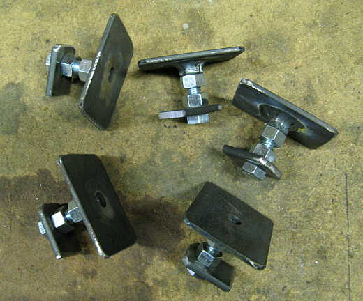
Here are the clamp assemblies ready to be welded to the car.
.................. .
.
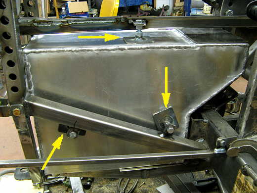
This shows the above pieces welded in. I kept the two bottom ones which are on both sides of the tank, but had to do away with the top one as it proved to be in the way when I added the filler to the tank and had to slide the tank up into this position.
.................. .
.
A vent/tip over valve was added to one side of the tank at the top.
.................. .
.
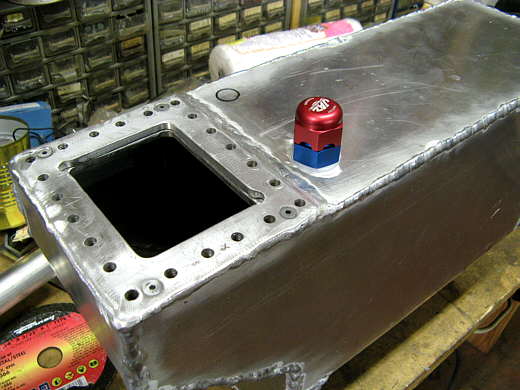
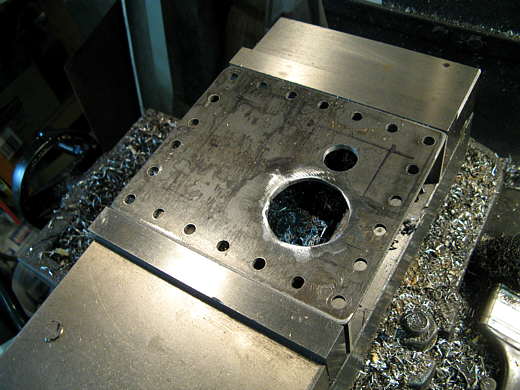
Two holes were put in the plate that seals the access to the tank. The large one is for the filler and the smaller one is for the return fuel line from the regulator.
.................. .
.
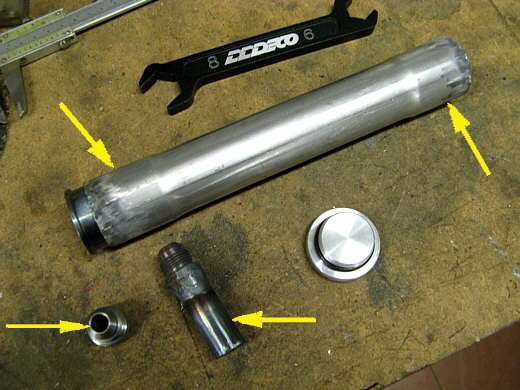
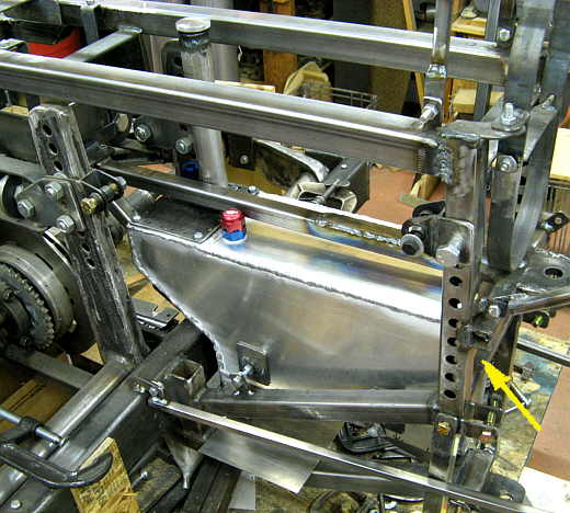
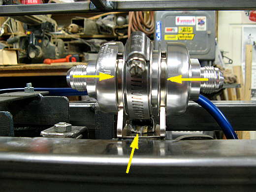
The two top arrows point to where the filler tube, exhaust tubing, was swedged out by my friend at the local machine shop. The cap and the piece the cap screws into to the left of the top left arrow came from Full Bore Racing. The bottom two arrows point to a piece of tubing that I welded a -8 AN fitting to. I'll put it in the return hole and then weld the other AN fitting (bottom left arrow) to it.
.................. .
.
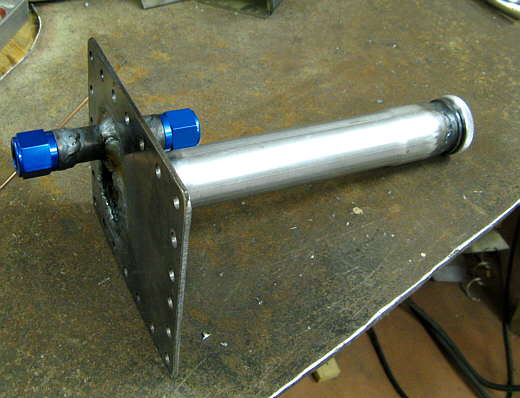
Here the filler tube has been welded into place and also the return has been welded into place. There is an AN fitting on the inside side of the return line so that I can add a piece of tubing in there to return the fuel to the front bottom of the tank.
.................. .
.
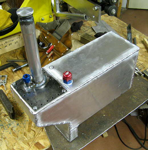
The tank with the filler, return and vent/tip over valve................. and...............
.................. .
.
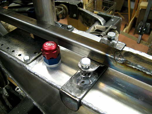
.............. installed in the car. To place it in the car the cross bar (right arrow) is removed and the tank is tilted at an angle to get the filler and vent up inside the car. Once those items clear the back the tank is then rotated parallel to the ground and slid forward into the space. This is all a tight fit. Once there the side clamps are screwed securely against the sides of the tank. Further down this page a top mount will be make also.
.................. .
.
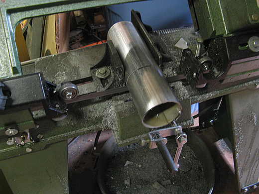
I need to make a mount to located the fuel pump and pre-filter along the bottom of the tank. A piece of tubing that is about the dia. of the pump was cut to length (above) and then that piece was cut in half lengthwise.
.................. .
.
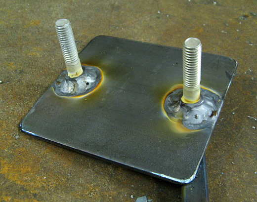
Two bolts were welded to a piece of strap.................. and .................
.................. .
.
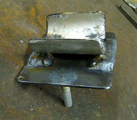
.................. the first piece was welded to the strap with a small riser that will allow a hose clamp to be placed around the pump.
.................. .
.
The pump mount was then mounted to tabs. The bolts allow the pump to be raised or lowered slightly to keep it in alignment with the outlet of the tank.
.................. .
.
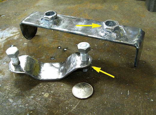
Here is the top mount. Once the tank is in position the top piece is slid in on top of the tank. The nuts welded to it have been drilled out and are just there to locate the bolts in the bottom piece. The bottom piece has threaded nuts welded to it for the clamping bolts.
.................. .
.
The clamp has to be removable to slide the tank in and out of the car. The top part of the clamp slides into place once the bottom piece is in place and then the bolts are threaded in and push down on the bottom clamp. With this clamp and the side ones the tank is very ridge in the car. It sits on some rubber strips and rubber will be placed between the top clamp and side clamps when the car is finished.
.................. .
.
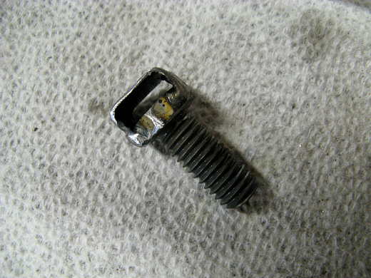
Next up was securing the 10 micron filter that is after the pump. I welded a "U-shaped" piece of 20 gauge steel to the head of this bolt. The TIG is really handy for pieces like this. I couldn't of done it with the MIG, well maybe if I had to.
.................. .
.
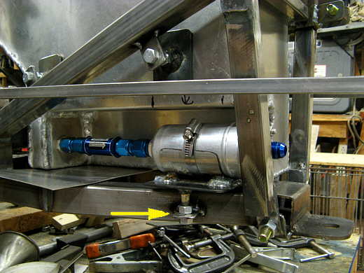
That bolt arrow is used to hold the mount that came with the filter to a tab that was welded to the frame. The arrows point to the two thin clamps that came with the filter and I didn't think much of them. The bolt I made lets me run a hose clamp through the top of it and really secures the filter.
.................. .
.
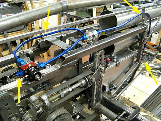
I also made a mount for the regulator (to the right of the lower left arrow). The top right and bottom right arrows point to the supply line coming from the pump/tank to the 10 micron filter and on to the regulator. Where the arrows are I also mounted rubber lined clamps to secure the 1/2 inch fuel line later (not in this picture). The top left arrow points to the return line back to the tank and the arrow points to one of the clamps that would receive a mount to bolt to. The bottom left arrow points to the outlet from the regulator where the line will go to the motor close by. This is a dead-head system.
..............................................................Next Page