...Return To Mine & Other Bonneville Car Construction Pages
.Previous Page...............B'ville Car Index Page.........................Next Page
................................-- Fuel Tank Part II --
.................
.................. .
.
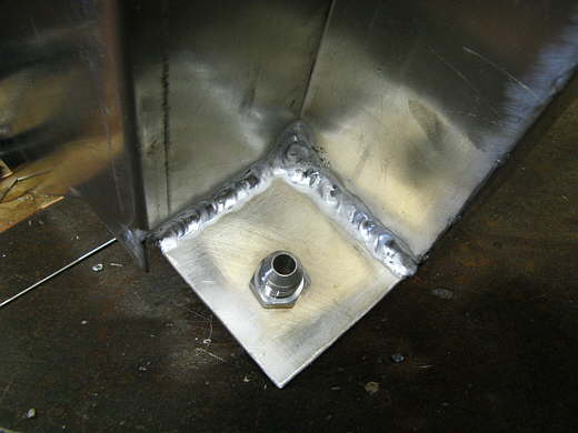
I received the weld in bungs I had ordered, so it was time to finish the tank. I had thought about making my own bung, but I haven't had real good luck tapping pipe threads, so I bit the bullet and ordered bungs for the fuel tank and the water tanks. Here I have welded the drain bung in the bottom of the tank (the tank is on it's side in the picture).
.................. .
.
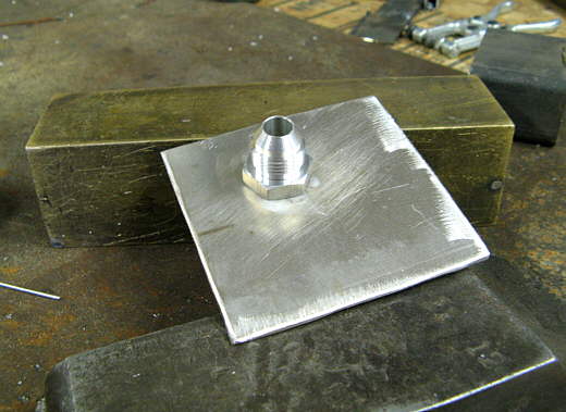
I drilled the right size piece of .090 that I'm using for the tank for the output bung. This one is an -8 AN fitting where the one in the first picture was 3/8 NPT. I wanted to preserve the flats on this fitting for a wrench, so I ..................
.................. .
.
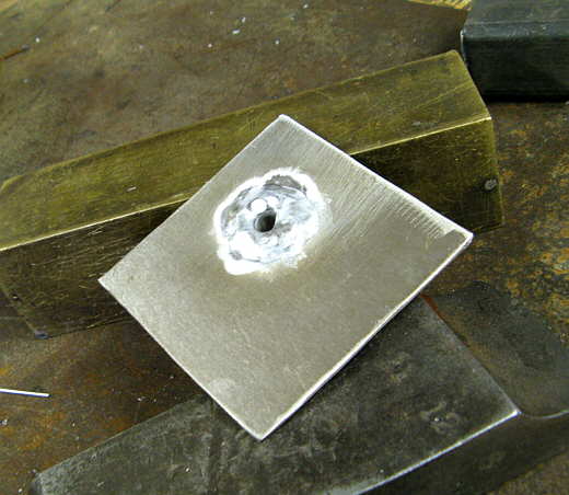
................ only welded it on the back side. The first one I welded on both sides.
.................. .
.
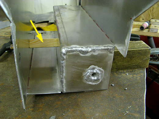
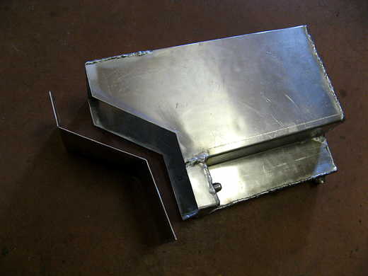
Then that piece was welded down in the front corner of the tank. The arrow points to a piece of wood that was just a spacer to try and keep the tank square while welding. Since this is only the second time I've welded aluminum with the TIG I decided to weld some of these on the inside and..............
.................. .
.
................... on the outside where possible. This fitting will attach to the fuel pump pre filter.
.................. .
.
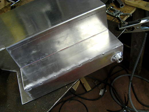
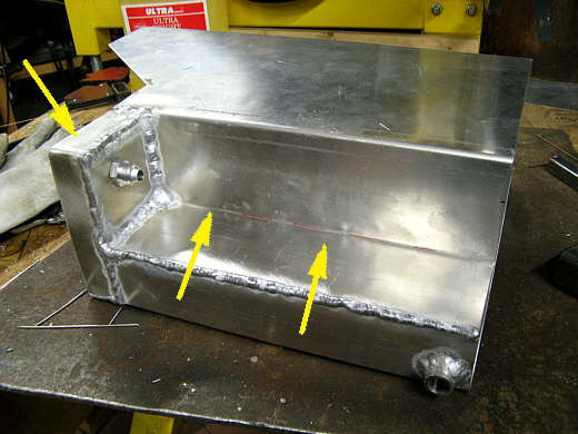
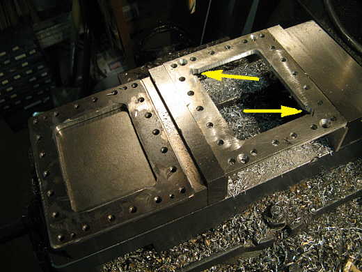
Next a piece was bent and welded in to finish that corner of the tank. The small area behind the fitting will be kind of like a sump. The two arrows point to where the fuel pump and pre-filter will be located. The tank is on it's side here. Since the output is above the bottom of the tank the tank will never run dry!!
.................. .
.
Following that work a piece was cut and welded to finish the back end (towards the rear of the car).
.................. .
.
I wanted some access to the inside of the tank and the filler, vent/tip over valve, and return line have to be removable to get the tank in and out of it's location on the car. I clamped a piece of 5 X 6 inch aluminum on top of a like size piece of 3/16 inch plate and proceeded to drill, counter sink and tap holes in the four corners. The hole in the aluminum is a little larger in diameter than a #10 screw and the hole in the steel is tapped 10-24. The aluminum will be welded to the top of the tank and the steel plate will be below it. Things will make sense in a few more pictures.
.................. .
.
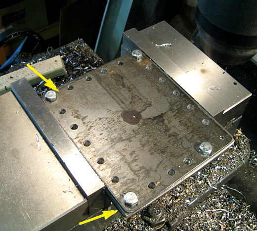
Here are the 4 10-24 screws that holds the steel plate below the aluminum one.
.................. .
.
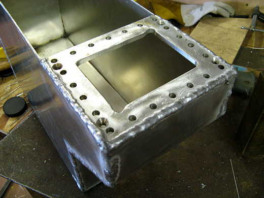
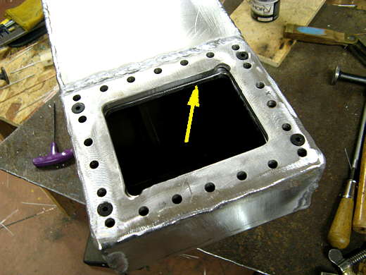
Now a third 1/8 inch plate has been put on top of the first two. The bottom arrow points to the 3 plate sandwich. The top arrow points to the area in the corners where the 10-24 screws are located under this plate. This plate will be the one that will be removed for access to the inside of the tank. Holes were drilled and tapped around the perimeter for 1/4 inch bolts and they will compress a gasket between the top two plates. 17/64th holes were drilled through the top two plates and a smaller hole went all the way through the bottom steel plate so that the bottom plate could be tapped for 1/4 inch bolts. I could of tapped the aluminum and done away with the steel bottom plate, but feel better with the threads in the steel plate.
.................. .
.
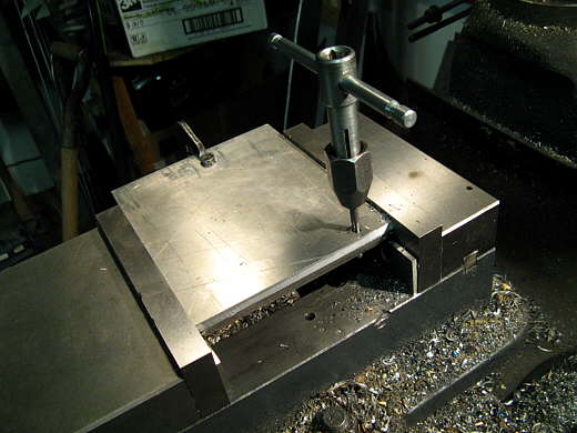
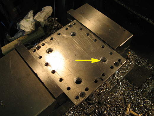
Now the top plate has been removed so that the access hole can be cut through the bottom two plates. I started the hole by drilling 4 1/2 inch holes at the corners (arrow points to one).
.................. .
.
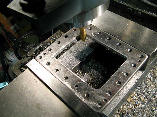
Next they were cut close to size with the plasma cutter and then put back in the vise on the mill and cleaned up one plate at a time. This is the steel bottom one with all of the tapped holes in it.
.................. .
.
Now the aluminum plate is in the vise getting finished. I also had to cut two slots diagonally from each other (arrows) so that there would be enough room to pass the steel plate down through the aluminum one later. You will see that further down the page.
.................. .
.
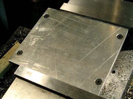
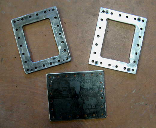
The three plates that make up the access to the fuel tank.
.................. .
.
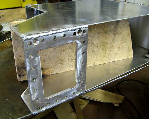
Here the aluminum plate is being positioned at the front of the top for welding.
.................. .
.
The plate welded to the sides. The particle board is again helping to hold things square.
.................. .
.
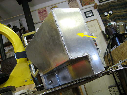
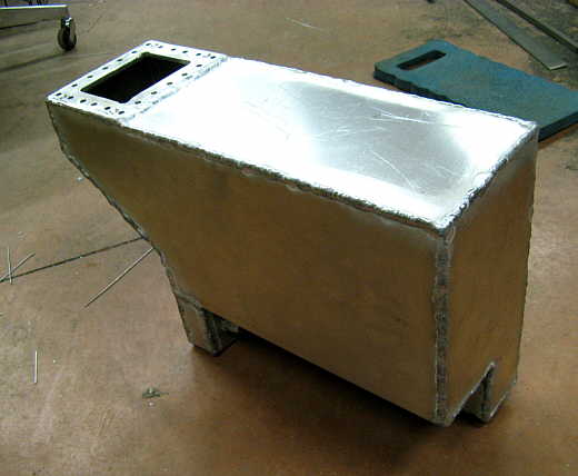
A piece was cut with the plasma cutter, ground smooth and bent to finish the front of the tank off. I wanted to weld the access plate in first in case I had a problem.
.................. .
.
Here the front has been welded into place. I use numerous clamps while doing this and tack it every couple inches before final welding. Also all the weld seams are brushed real well with a stainless brush to remove the oxidation. If you do that and keep everything really clean the welding goes pretty good even for a beginner like me. My aluminum welds could still be quite a bit better though.
.................. .
.
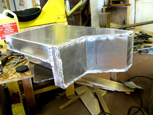
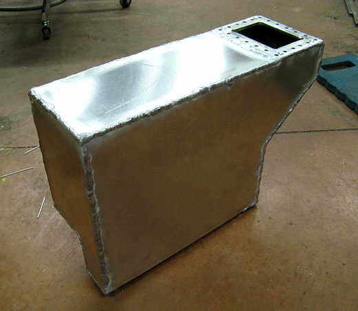
So now finally the tank is getting near completion. A piece........................
.................. .
.
.............. was cut and welded in to finish the top. You can see the recess on the bottom where the electric fuel pump and pre-filer will reside.
.................. .
.
A view of the other side.
.................. .
.
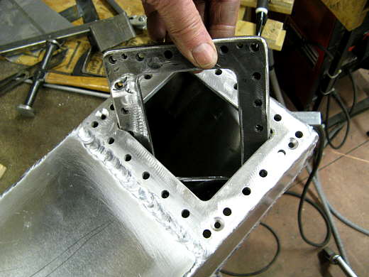
Here I'm putting the threaded steel bottom plate in the tank and you can see the reason for the two cut-outs in two of the corners of the aluminum plate.
.................. .
.
The steel plate is in place (arrow) and held there with the 4 10-24 screws in the corners. Next a gasket would be put into place......
.................. .
.
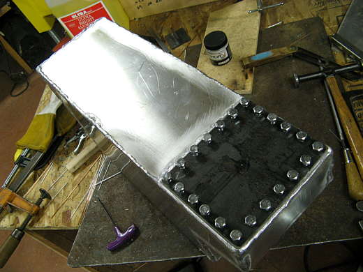
................... and the top would be bolted down with lots of bolts. Pardon me for not putting them all the way in for this picture. The fuel neck/cap assembly will be welded to this plate along with the return line from the fuel regulator.
..............................................................Next Page