...Return To Mine & Other Bonneville Car Construction Pages
.Previous Page...............B'ville Car Index Page.........................Next Page
.........................................-- Push Bar Again --
.................
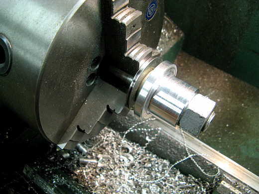
I went to the auto parts store and said I was looking for a sealed bearing
about 3 inches in diameter and about 1 inch thick to put on the back of the push bar that the push truck will push
against. They came to the counter with one that was on a shelf and had no box or part number and asked what I would
give for it. $10 got the bearing.
.................. .
.
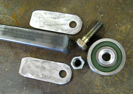
The center was too big for a 3/4 inch bolt, so I turned this bushing out of aluminum on the lathe.
.................. .
.
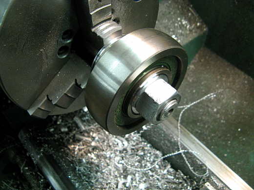
Here is the bushing with the bearing slid onto it.
.................. .
.
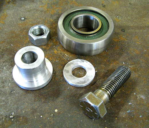
I also made the washer in the middle of the picture so that the bearing, bushing, washer were the 1 1/2 inch total thickness I needed to fit on the back of the push bar.
.................. .
.
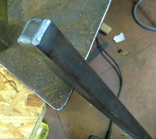
Since the car was now longer I need to build an extension to add to the previous push bar. I used some 1 1/2 inch square tubing and capped the end as I like to exclude salt from any inside surfaces wherever possible.
.................. .
.
I took a piece of small square tubing to act like a sleeve on the end that would hook to the previous built push bar. Since the square tubing as a slight weld seam inside of it I milled a small groove to clear that weld seam. It is on the bottom and not shown here. I also had to grind on the smaller piece slightly to get it to slip into the other two pieces.
.................. .
.
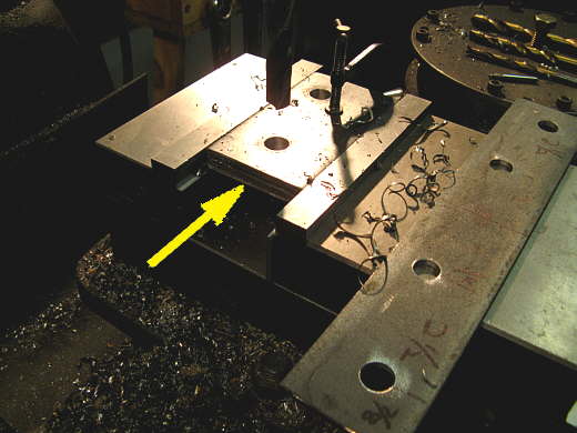
Two tabs were made for the end to hold the roller assembly.
.................. .
.
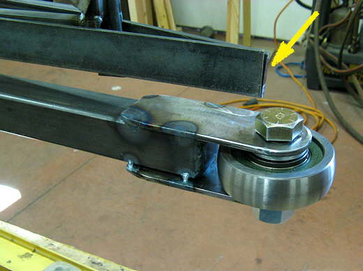
The arrow points to what should be the very back of the chute doors and thus the very back of the car. The roller will stick out the back slightly.
.................. .
.
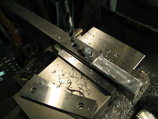
To finish the junction of the push bar extension to the previous one I drilled two 1/2 inch holes through the larger square tubing and inner tubing. Besides being pushed on this joint will be in tension when the chute deploys as the lower chute attach point will be on this new extension.
.................. .
.
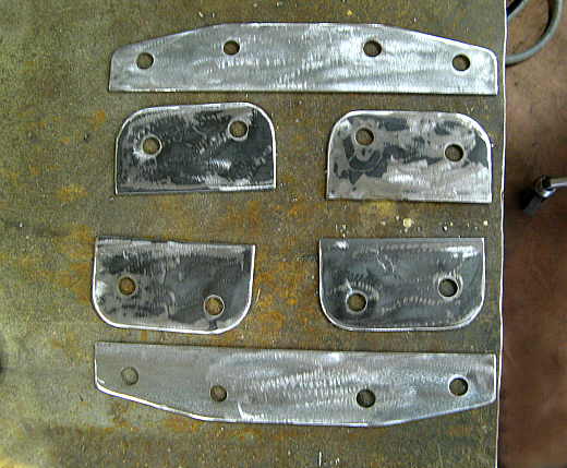
To further strengthen this joint I made two of these pieces to span the joint.
.................. .
.
And four other pieces that are welded on each side of the joint and each side of the square tubing.
.................. .
.
The four brackets after they have been drilled and shaped to fit into place.
.................. .
.
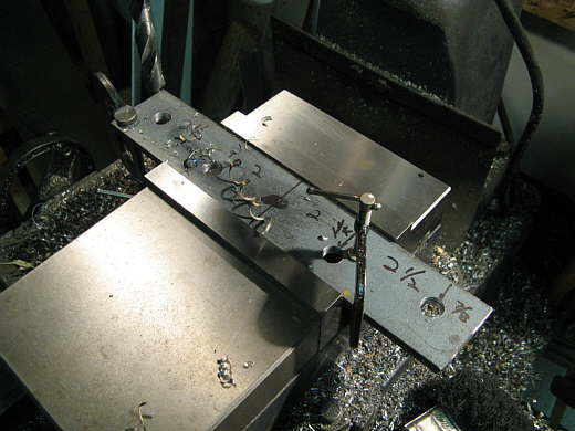
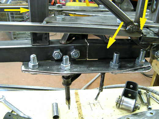
The shorter brackets were welded to the square tubing on both sides of the joint and also both sides of the car. The longer plates span the joint. The top right arrow points to the chute door where it meets the body. The front of the car is to the right in the picture. The left arrow points to the new upright that the chutes will connect to. The next page will go into how it was built.
..............................................................Next Page