--- The Stude's 2013 Changes Page 6 --- --- Mounts for Twin Turbos --- |
The two turbos chosen for the car are Borg Warner SX400's (#171702) and came from Turbochargerpros.com in Calif. who were prompt with delivery and had good pricing. These aren't the best turbos for this size engine but should be good for 1600 H.P. or more and are no where near the price of the next larger turbos. If you didn't see it, how we arrived at these turbos is ( HERE ).
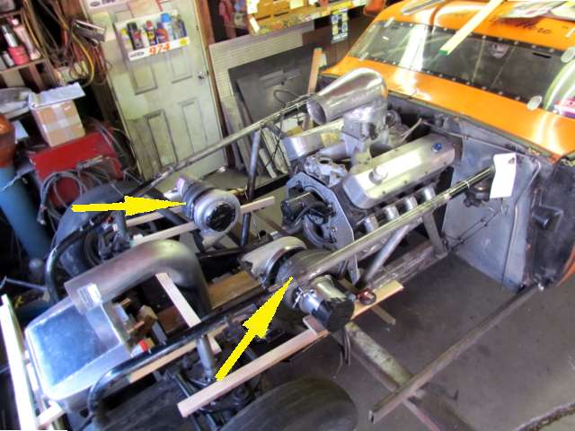
Hooley blocked the turbos into place with some lumber. The position was chosen since the headers can feed directly into them with no 90 degree bends and the compressor outlets are aimed right at the two intercoolers forward in the nose of the car. The exhaust will be down into and out the front wheelwells and ....
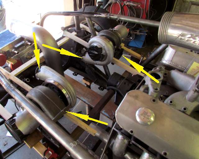
... they will share a common inlet from the front of the car, represented above by the 5 inch 90 deg. elbow to the left in the picture above. The two right arrows represent the exhaust path to the turbo's turbine section. The top left arrow points to the compressor outlet going forward to the intercooler on the driver side.
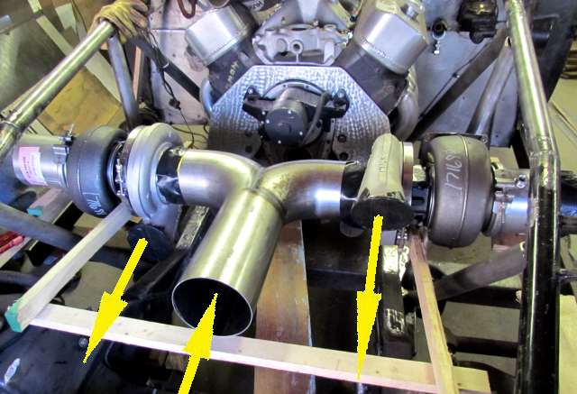
Hooley found the "T" pipe at Chrome Shop Mafia along Interstate 44 in Joplin, MO. The width of the top of the "T" pretty much determined the distance between the turbos. A box type plenum was considered there but for now this will be a starting point. Using the "air inlet size" spread sheet on this site the 5 inch dia. pipe should provide enough air for our anticipated air requirements for now.
The headlight openings were also in the running but for now the plumbing from them was too complex for the time schedule to hopefully get the car on the salt this year (2013).
Note that with the turbos facing each other the compressor outlet is on the top on one and the bottom on the other. The turbine inlets are similar. You can clock them to any point in a 360 degree circle with the band clamps that connect the center section to the outer sections.
Using the lumber supports at this point makes it easy to try different positions for components and provides supports while the more permanent metal brackets are fabricated.
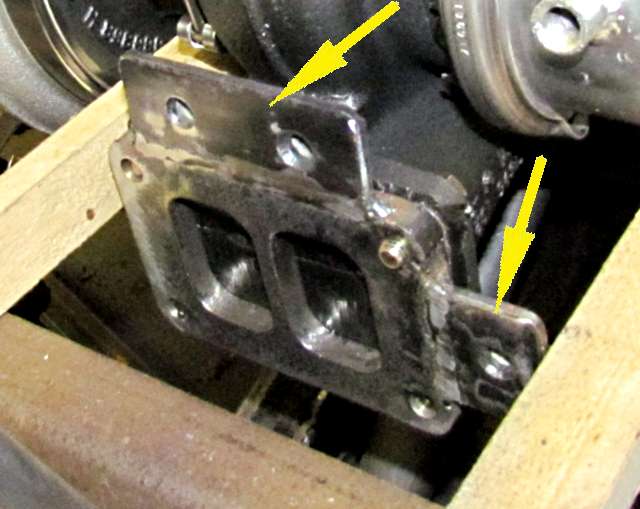
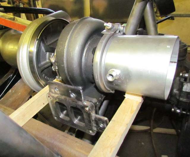
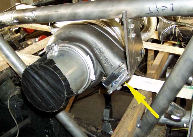
Hooley purchased flanges that the turbos will be mounted to on one side and the headers on the other. He welded tabs (arrows) to the flanges for the brackets to bolt to. You can buy flanges with tabs on them.
Above the passenger side turbine/flange is clocked to a position facing the side of the block in anticipation of connecting the header for this side of the engine to it.
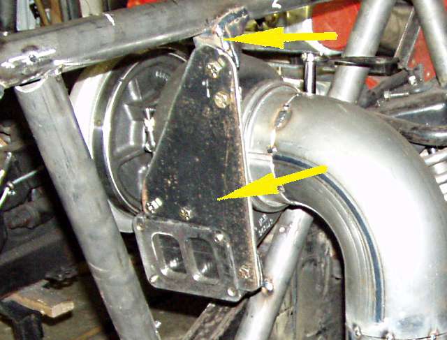
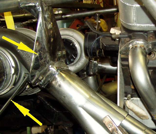
Tabs (top arrow) were welded to the top frame rail and then a bracket was cut that connects the turbo and its flange to the tab on the frame.
Also diagonal supports (bottom right arrow) were run from a frame member up to the turbo flange to triangulate the mount.
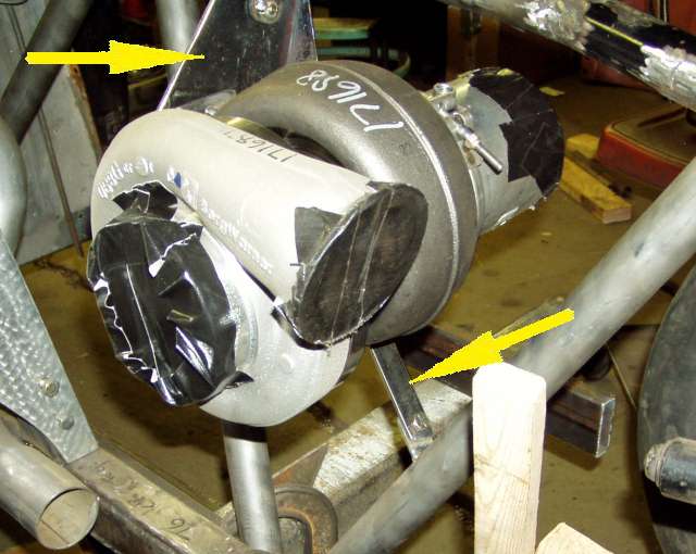
Another view of the mounting bracket, left arrow. The middle arrow points to the 5 inch exhaust (more on that on another page). The right two arrows point to the band that lets you clock the turbing (similar one on the compressor side) and a ratchet for loosening/tightening the band.
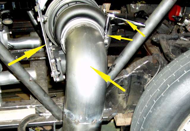
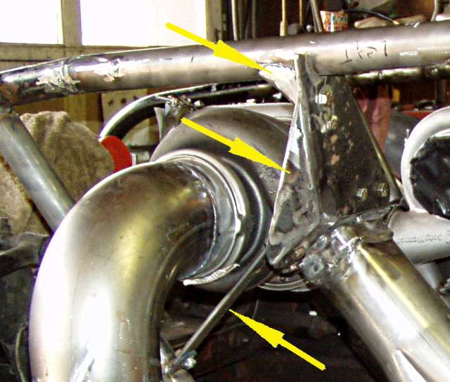
The other turbo was mounted mostly in the same manner using the flange with the tabs on it but since this turbo is clocked somewhat different so that it can point at the header on this side of the engine the bracket is a little different that goes to the frame member.
Notice that it also has a diagonal support, bottom arrow but since it has a bend in the top bracket another piece was welded in, top arrow, that really stiffens it up. Here we can see that a collector has been welded to the flange at this point also.
Another view of the main turbo support components for this side of the car.