--- The Stude's 2013 Changes Page 29 --- --- Innovate Data Logging --- |
For 2013 we added quite a bit to the car in the way of data logging. 16 total inputs are now data logged.
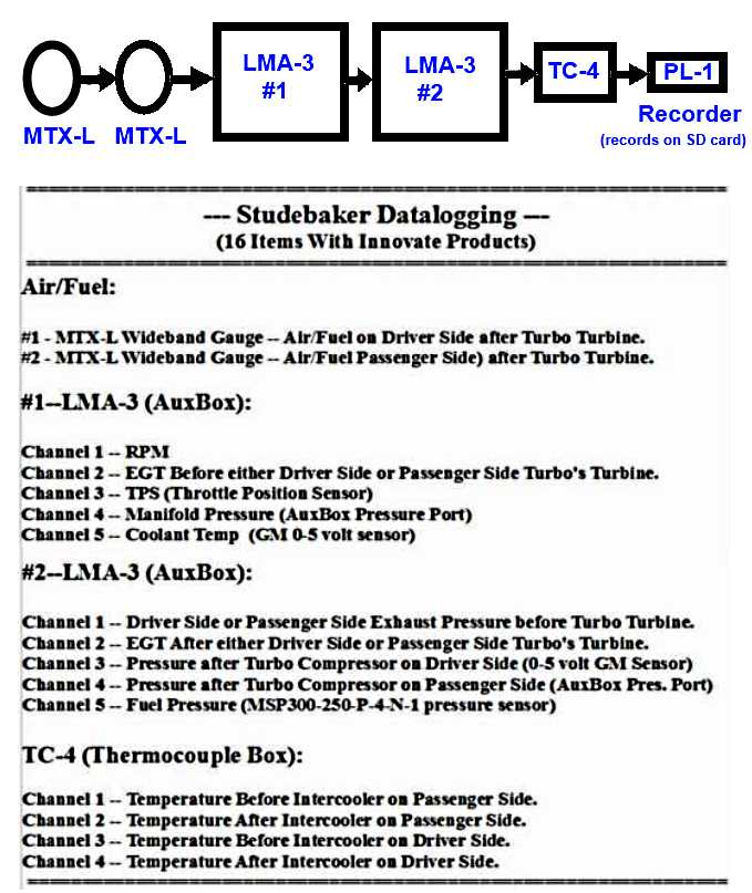
Innovate uses a chain type setup for sending the data along to the PL-1 recorder at the right side of the chain above or to a computer if it replaces the PL-1.
In our case, shown above, the data from the first MTX-L (air/fuel), on the left, goes to the one to the right where that one's data is added to the data packet and passed on to the the first LMA-3, where its data is added to the packet and so forth until the data from the second LMA-3 and the TC-4 arrives at the end of the chain where it is collected by either the PL-1 Data Recorder (uses an SD card) or by a computer if you have it connected instead of the PL-1.
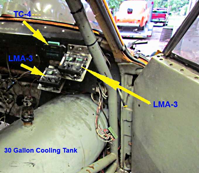
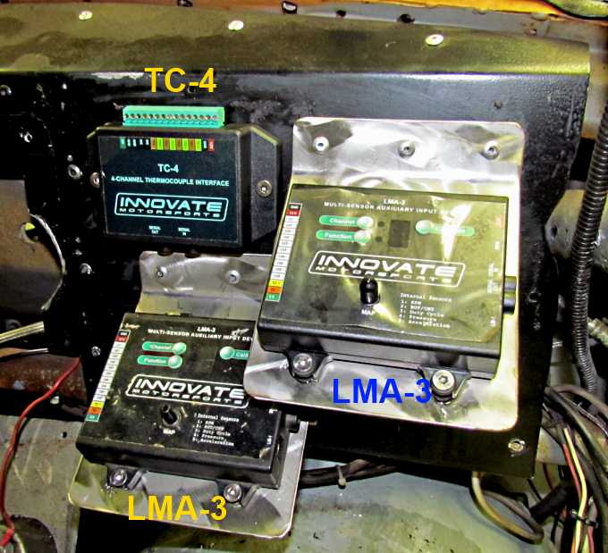
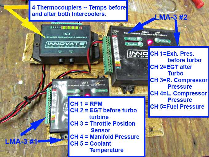
Above you can see the new Innovate Motorsports TC-4 (4 thermocouples) and an additional LMA-3 (two total now). Out of view on the left side of the dash are 2 new MTX-L wide band O2 controllers/gauges that were also added to the car in 2013.
Brackets were made to group the TC-4 and the two LMA-3's next to the door on the passenger side.
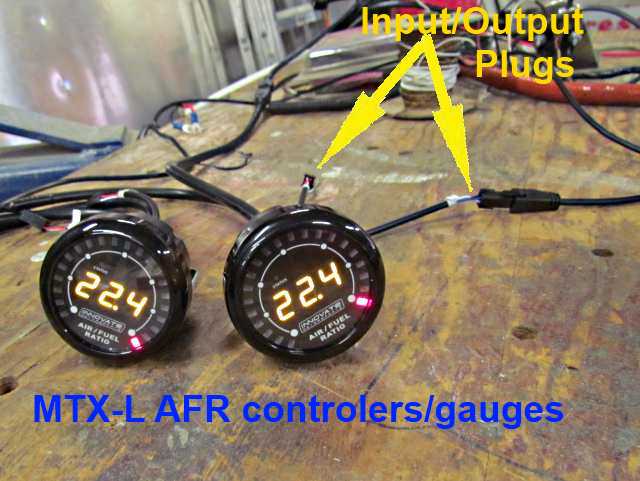
The two MTX-L's shown with the standard startup reading without the engine running. There is also a ring of LED's circling the gauge that go from green to amber to red if the air/fuel goes lean. Notice the last red LED is now lit on both gauges. You can program the gauge to change from one color to the next at whatever threshold a/f ratio you want.
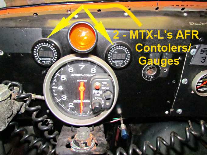
The two gauges went into the dash on either side of the tach. They are bright and you can read them even at b'ville if you aren't busy with other stuff. You don't need to read them as they are being data logged always if the data recorder is running.
The boxes above show what we are data logging at the present but there are a lot of options and you can choose to data log about any device you could have on the car.
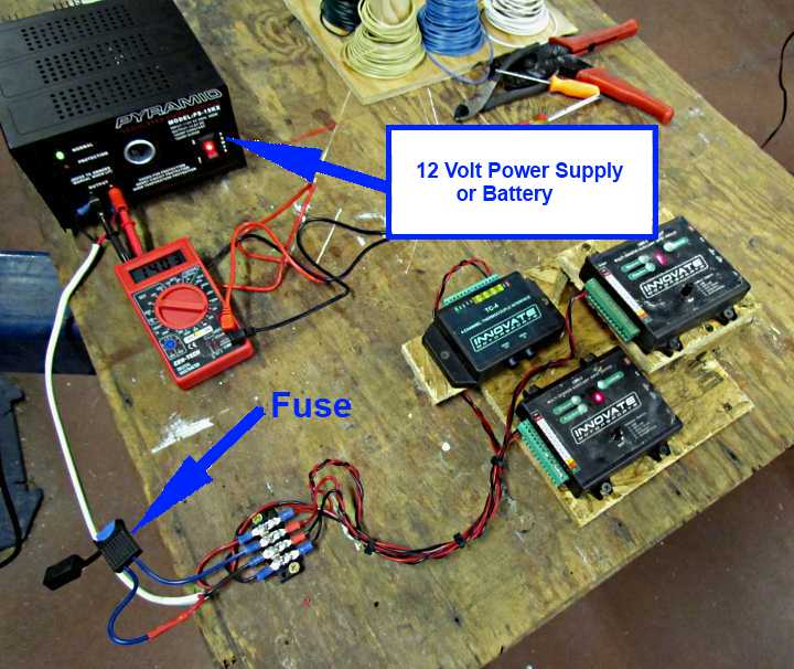
I wanted to connect to all the sensors out of the car first so setup a temporary test station.
I used a 12 volt power supply I had but a battery could also of been used.
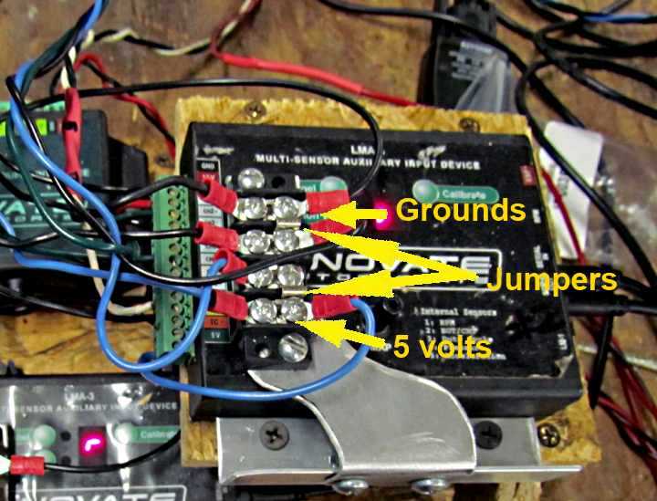
I added terminal strips that help with the wiring as you need to run a number of grounds and sometimes a number of 5 volt inputs to sensors depending what you are using.
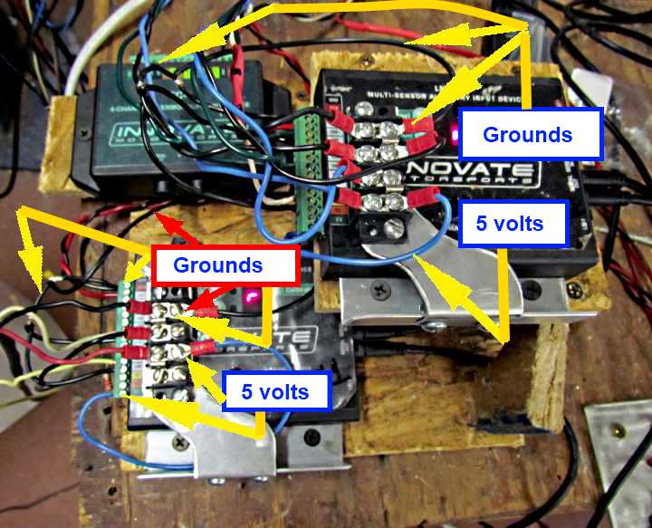
There are 4 posts for grounds and 4 posts for 5 volts on each terminal strip. I use these for the grounds for the 5 volt sensors. There is a ground lead from the terminal strip (right side of it) that goes down to what I'll call a ground loop. One end of the ground loop goes to the GND terminal on the LMA-3 (green bar) and the other goes the Channel Negative for those devices that input a 0-5 volt signal to the LMA-3 like the TPS and Coolant Sensor being recorded above. Also there is a ground wire off that loop going up to the terminal strip mounted above the LMA-3. Sensor grounds go to it. This ties all the grounds to the GND connector on the LMA-3.
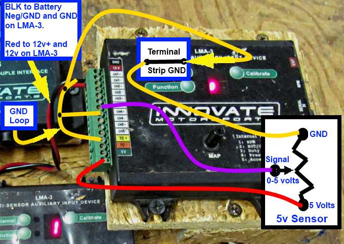
Here is a less cluttered example as this can be confusing..
The top two connectors on the LMA-3's connector strip are the main GND and the 12 volts in to the device (BLK & RED wires). For any sensor that is 5 volts and gives a 0-5 volt output signal you need (see example, lower right above) a 5 volt input, bottom post, a sensor ground, top post, and you will have a 0-5 volt output signal.
We get the 5 volts from the bottom of the LMA-3, red wire. The output, purple wire, goes to the CH+ of the channel we are using with the LMA-3. In this case the output is going to CH3+ which is going to log our TPS (throttle position sensor). The sensor ground is going to go to the terminal strip mounted above the LMA-3 and from it down to the ground loop where the wire is soldered to the ground loop. Notice there is also a wire soldered to the ground loop that goes to CH3-. The LMA-3 does not ground the input signals after it processes them internally. This is important. If we input voltage to CH3+ we have to ground CH3- back to the main GRN at the top of the LMA-3. The ground loop does this as one end is going to the main LMA-3 at the top. It is under the ground that goes back to the negative side of the battery.
In the diagram above I also show the ground loop ending at CH5- which is for the coolant sensor. I didn't show the input going into CH5+ to avoid confusion at this point. You will see it in some of the other pictures.
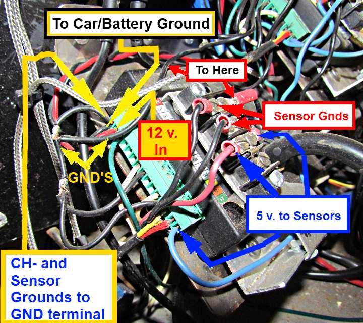
The important thing to remember is that sensors themselves need to be grounded and signals from them that go to the LMA-3 need to also be grounded via the CH- terminals.
Study the pictures below if there is confusion.
You can use very small wire sizes, like 18-20 or even 22 as we are not talking a lot of current here. The holes in the green connector or very small and I only like putting one wire in them except for the GND with the GND feed and the GND loop going in it. I have put the sensor ground (negative) wire in with the CH- ground but didn't like it as it is hard to service and I think more prone to failure if the wires move. Get a good screw driver to use for the screws in the green strip. The green strip connector is the main pain if dealing with the LMA-3 in my opinion but using the additional terminal strip for sensor grounds and 5 volt feeds makes it easier to live with.
If these and other connections aren't sound and good you will fight your data loggin.
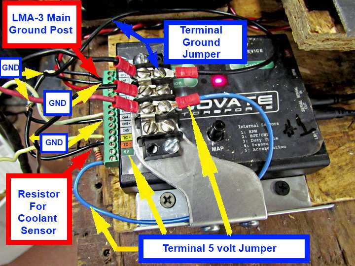
Above you can see the red 12 volt power feed and the GND feed with the GND loop also in the same hole next to the 12 volt feed.
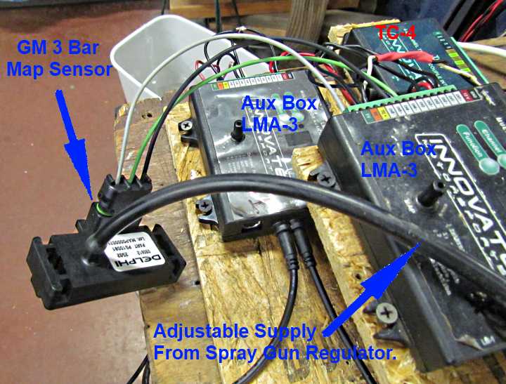
The two wires next to the blue 5 volt-out wire are going to a thermocouple. Between the Red Box to the right and the Blue Box to the right is a tube going to the internal pressure sensor being used for manifold pressure with this LMA-3.
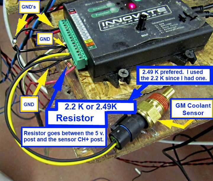
CH5 (channel 5) on this LMA-3 is being used to log coolant temps. With the GM sensor you need to add a 2.49K resistor between the 5 volt output and the CH5+ position. I had a 2.2K resistor and it was close enough and worked. Testing it above I had the sensor negative, blk wire, going to the CH5- position along with the required GND going back to the LMA-3's GND terminal via the GND loop. Later I moved the sensor ground up to the terminal strip on the GND side there so that I didn't have to secure two wires in the CH5- position.
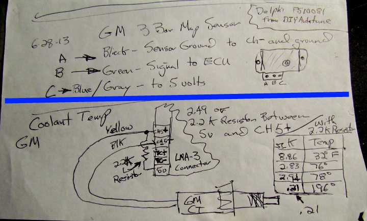
Above is information on how the coolant sensor is wired. I show the black lead going to the CH- and that will work or wire it to the GND side of the terminal strip which also is tied to the LMA-3's ground.
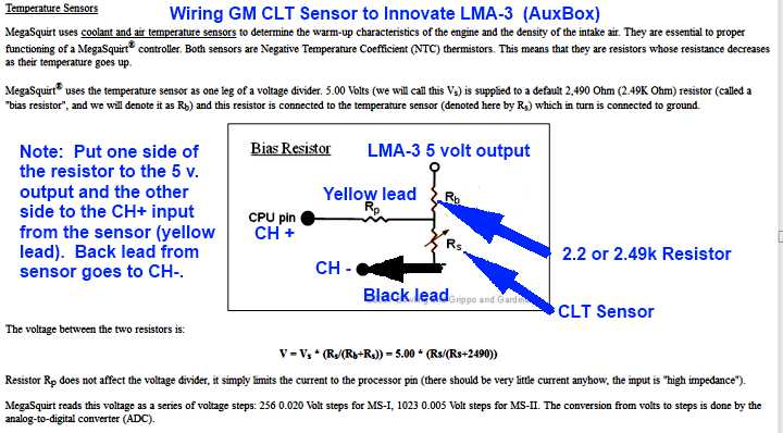
An example of how to wire a GM 3 Bar Map Sensor to the LMA-3. We use some of these and also more info on the Coolant Sensor. You will need to calibrate the LMA-3 by using ice water and boiling water and another know water temp. This can be done in the shop before putting the sensor in the car.
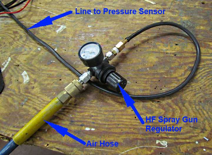
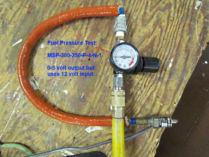
I checked the pressure sensors, both internal and the GM 3 Bar using a cheap regulator meant for a spray gun (Harbor Freight). One side connects to the air hose and the other goes to the sensor. You can regulate the pressure up and down and calibrate easily. While I'm doing this I have the LMA-3 connected to the computer via a serial cable and a USB to serial adapter and the computer is running Innovate's Log Works.
Here the line from the air hose/regulator is connected to a GM sensor.
Here I'm testing/calibrating the fuel pressure that the LMA-3 is reading. This sensor didn't work for us the first year we tried it but that was because I screwed up and was powering it with 5 volts. It is different in that it is powered by 12 volts but puts out a 0-5 volt signal. Check your sensors and don't take things for granted like I did.
Don't think you are going to be buying data logging gear and using it the first week. It takes some time to figure out how to set some of this up and then how to read it, but if you take the time you will save a lot of money on broken parts and wasted time down the road. It isn't going to erase all of your sins but will ease them in most cases,
Sum