Return
to Sumner's Home Page
.......Under Construction Page One.................................Under
Construction Page Three
FRAME DETAILS
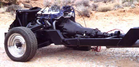 Sub-frame Detail: These first two pictures will
give some details of the '73 Camero sub frame and main frame. In the first picture you can see how the frame drops
in the middle. The original frame went straight across from the right side of the picture to the sub-frame on the
left side. I then decided that I needed some more leg room in the cab as the cab is sectioned 6 inches (6 inches
were removed from the center of the body all the way around lowering the top of the cab by 6 inches along with
a 3 inch top chop). I wanted to drop the cab floor by about 6 inches to make up for what I removed from the body
(you can see this in later pictures). I took a piece of 2X4X1/8 square tubing and put it under the original frame
in this area. The original frame was 6 inches deep so this mean the new center section of the frame would be 6
inches lower than before. I then put gusset plates at the front and back of this section (they are the angled sections
in the photo where the frame is Z'd). After the new section was solidly welded in I cut out the old frame above
it and welded in some more gussets to fill the gaps where the old frame use to be.
Sub-frame Detail: These first two pictures will
give some details of the '73 Camero sub frame and main frame. In the first picture you can see how the frame drops
in the middle. The original frame went straight across from the right side of the picture to the sub-frame on the
left side. I then decided that I needed some more leg room in the cab as the cab is sectioned 6 inches (6 inches
were removed from the center of the body all the way around lowering the top of the cab by 6 inches along with
a 3 inch top chop). I wanted to drop the cab floor by about 6 inches to make up for what I removed from the body
(you can see this in later pictures). I took a piece of 2X4X1/8 square tubing and put it under the original frame
in this area. The original frame was 6 inches deep so this mean the new center section of the frame would be 6
inches lower than before. I then put gusset plates at the front and back of this section (they are the angled sections
in the photo where the frame is Z'd). After the new section was solidly welded in I cut out the old frame above
it and welded in some more gussets to fill the gaps where the old frame use to be.
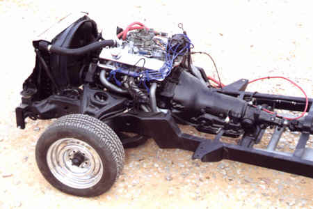 In the picture to the left you can see how the
cab mounts were welded onto the new frame section of 2X4 square tubing. I also raised the engine mounts about 1
1/2 inches to give the headers a little more clearance. The headers are Hedman and are for sub-framed cars and
have good clearance at the collectors after I raised the engine. I raise the engine since I am running 185X60X14
inch tires in the front which are probably 2 to 3 inches smaller in diameter than the tires found on Camero's of
this time period (Sub-frame is '73 Camero front steer). I also welded in pads on each side of the frame for the
rear transmission mount cross member. They are about 1 inch lower than what I thought was the right angle and have
spacers that make up this difference. This will allow me to have some flexibility over the height of the rear of
the transmission for drive line angle purposes in that I can raise or lower the rear of the transmission by adding
or removing spacers on these pads. The front shocks are Carrera and are 50/50 dampening for Camero's. I had some
problems with the rear portions of the front fenders sometimes hitting the pavement at speed on roads with sever
dips. The 50/50 action of these shocks slowed up the compression of the front springs in these situations. No more
clearance problems. Never though I would pay $180 for 2 shocks, but they have been a very good investment and I
like the way they stiffen up the ride a little. I hope to add some more to the rear at a later date (see below).
In the picture to the left you can see how the
cab mounts were welded onto the new frame section of 2X4 square tubing. I also raised the engine mounts about 1
1/2 inches to give the headers a little more clearance. The headers are Hedman and are for sub-framed cars and
have good clearance at the collectors after I raised the engine. I raise the engine since I am running 185X60X14
inch tires in the front which are probably 2 to 3 inches smaller in diameter than the tires found on Camero's of
this time period (Sub-frame is '73 Camero front steer). I also welded in pads on each side of the frame for the
rear transmission mount cross member. They are about 1 inch lower than what I thought was the right angle and have
spacers that make up this difference. This will allow me to have some flexibility over the height of the rear of
the transmission for drive line angle purposes in that I can raise or lower the rear of the transmission by adding
or removing spacers on these pads. The front shocks are Carrera and are 50/50 dampening for Camero's. I had some
problems with the rear portions of the front fenders sometimes hitting the pavement at speed on roads with sever
dips. The 50/50 action of these shocks slowed up the compression of the front springs in these situations. No more
clearance problems. Never though I would pay $180 for 2 shocks, but they have been a very good investment and I
like the way they stiffen up the ride a little. I hope to add some more to the rear at a later date (see below).
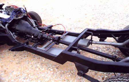 In this photo you can see the drive line loop and
the center cross member with exhaust hangers. The exhaust is a dual exhaust system from J.C. Whitney for 70's Camero's
that I cut up and re-welded together. The mufflers are (I believe) Thrush turbo truck mufflers that according to
Hot Rod flow about the same as the expensive ones. I cover the exhaust from headers to tailpipe with Eastwood stainless
paint. It has held up pretty good for about 90,000 at this point (JUL. 2001). I wish I would have also coated the
insides (tape tennis balls on the ends and put paint in the pipe and tip it back and forth).
In this photo you can see the drive line loop and
the center cross member with exhaust hangers. The exhaust is a dual exhaust system from J.C. Whitney for 70's Camero's
that I cut up and re-welded together. The mufflers are (I believe) Thrush turbo truck mufflers that according to
Hot Rod flow about the same as the expensive ones. I cover the exhaust from headers to tailpipe with Eastwood stainless
paint. It has held up pretty good for about 90,000 at this point (JUL. 2001). I wish I would have also coated the
insides (tape tennis balls on the ends and put paint in the pipe and tip it back and forth).
 None of the crossmembers on the frame are stock. Also all that is left of the stock frame
is the rear parts of the frame rails from right in front of the front hangers for the leaf springs to the rear
of the frame. All holes were filled and the inside of the frame is filled in (boxed) with pieces of 1/8 inch plate.
The front spring mounts were cut off the Camero donor car. The rear are a combination of the Camero and pipe of
the right inside diameter for the stock bushings. The Shocks are air shocks and work well for changing the ride
height for different load conditions. They also enable me to pull the tires/wheels off the truck. Since the truck
sits so low in order to change a tire I air the shocks up all the way. This raises the bed and rear fender above
the tire. Then I put a jack under the axle to raise the tire off of the ground and then remove it. I am thinking
about staying with the leaf springs ('73 Camero) and using air bags to control the ride height. This will let me
go to a better shock in the back.
None of the crossmembers on the frame are stock. Also all that is left of the stock frame
is the rear parts of the frame rails from right in front of the front hangers for the leaf springs to the rear
of the frame. All holes were filled and the inside of the frame is filled in (boxed) with pieces of 1/8 inch plate.
The front spring mounts were cut off the Camero donor car. The rear are a combination of the Camero and pipe of
the right inside diameter for the stock bushings. The Shocks are air shocks and work well for changing the ride
height for different load conditions. They also enable me to pull the tires/wheels off the truck. Since the truck
sits so low in order to change a tire I air the shocks up all the way. This raises the bed and rear fender above
the tire. Then I put a jack under the axle to raise the tire off of the ground and then remove it. I am thinking
about staying with the leaf springs ('73 Camero) and using air bags to control the ride height. This will let me
go to a better shock in the back.
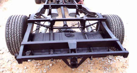 Looking
at the frame from the back you can see something I am proud of, but no one really notices. That is the design work
I did to have a heavy duty carrier for the hitch (I have pulled trailers up to 6000# with the truck) and to also
let the inlet for the gas tank both reside behind the license plate. The tank is out of the donor Camero. I had
to put the rear springs at a slight angle (mounts wider at the back than the front) to allow the tank to fit, but
it has not hurt the ride or handling.
Looking
at the frame from the back you can see something I am proud of, but no one really notices. That is the design work
I did to have a heavy duty carrier for the hitch (I have pulled trailers up to 6000# with the truck) and to also
let the inlet for the gas tank both reside behind the license plate. The tank is out of the donor Camero. I had
to put the rear springs at a slight angle (mounts wider at the back than the front) to allow the tank to fit, but
it has not hurt the ride or handling.
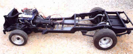
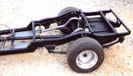
View of complete chassis. I am very happy with the way the truck handles and
rides. It is great on mountain roads or going down the interstate long distances.
- - - - - - - - - - - - - - - - - - - - - - - - - - - - - - - - - - - - -
- - - - - - - - - - - - - - - - - - - - - - - - - - -
NOTE: I Added the following on 03 24 05 as I had a request for more information
on how I made the hitch receiver. At the time these pictures were taken the truck had 120,000 miles on it and
was on the salt at Bonneville a number of times, so there is rust and dirt.
................................
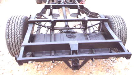
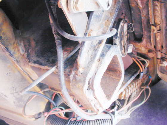
I took the picture further up the page and lightened it up a little to help
see the detail better. At the very rear is a smaller square tubing crossmember that if I remember right is about
1 1/2 X 1 1/2 and 1/4 inch wall. The purpose of it is to help support the tongue weight on the hitch and give
lateral support to the hitch with the two diagonal pieces from it down to the receiver.
In front of the rear crossmember is the main crossmember and it is 1/8 X 2
X 4. It ties into the frame rails. In the center of it are two piece of flat steel that are welded onto the crossmember
and go down at an angle to the receiver. These are the main supports for the receiver.
The gas filler tube is in the middle of these pieces. Another piece of flat
stock wraps over the top of the cross member and down the top of the two main support pieces just mentioned. It
supports them and ties them into the crossmember. These flat pieces are all 1/4 inch if I remember right.
..............................
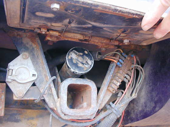
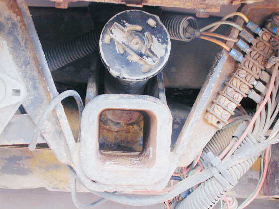
Here I am holding the license plate up with my hand. You can see a junction
block on the right with the wiring harness from the cab on the left and the wires to the lights and trailer socket
on the right. If I have to remove the bed from the frame this junction block comes in handy. In the middle top
is the filler for the gas tank with the receiver below it. On the left is the socket for the trailer lights.
..............................
The Diagonal braces were made with a piece of strap that is welded flat to
the rear crossmember for a couple inches then bent at an angle down and around the bottom of the receiver and then
back up at an angle and welded back onto the rear crossmember on the other side. I then cut long triangulated
pieces of flat stock and welded those onto the piece of strap on both sides to reinforce/stiffen the whole thing.
The trailer socket is hooked onto one of these pieces on the left side and the electrical junction box is hooked
on to the triangular piece on the right side.
..............................
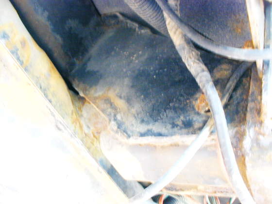
In this view the gas tank is to your left. In the center-top of the picture
is one of the pieces of strap that is welded on the top to the main crossmember and on the bottom to the receiver.
This and the one on the other side are the main supports for the receiver and transmit the pull on the receiver
up to the main crossmember. They also help share the load from the tongue weight that is put on the receiver.
The receiver bottom is the light area with the diagonal CB antenna wire crossing it. On the far right you can
just make out one of the diagonal braces coming down from the rear crossmember.
............................
My safety chains for the trailer go around the back side of the two diagonal
braces from the bottom. They then come forward through the "V" area on both sides of the receiver and
hook onto the diagonal braces with a hook on the end of the chain. They are then kind of wedged down into that
"V" shaped area. That has worked well and they have never come off in over 40,000 miles of towing.
This whole hitch/gas tank filler setup has worked very well and I've pulled
some trailers over 6000 lb. and 300-400 lb. of tongue weight with it. I would do it again the same way.
Under construction Page Three