Return to Tech Info Page..............................Return to Sumner's Home Page
.................................................... Next Page of 700R4 info.
.................................................... 700R4
Information
PLEASE READ THIS: I am not a transmission
repairman. I use a 700R4 in my truck and have accumulated the following information that might help you. A lot
of problems with this transmission after installation are due to improper TV cable hookup and adjustment. I have
that info here along with wiring information for the lockup converter. If you are having internal problems with
the transmission I'm sorry, but I can't help, so please don't e-mail me about those kind of problems. You need
to talk to a repairman or you might trying posting on Rodder's Roundtable Forum and post the question
to Tony (board name is Crosley). He works on these transmissions all the time and you can trust his answers.
It is very important to set up the Throttle Valve (T.V.) cable linkage properly to prevent damage to your
transmission. I can't stress how important the geometric relationship of the hook up point on the carb for the
T.V. cable is with this transmission (see following pages). All of these distances and angles will determining
where the cable is at close throttle and WOT and all points in between. If they aren't right it is going to be
hard to get the transmission to shift right under all load combinations and you sooner or later you will be fixing
the transmission. This is a great transmission. Take the time to set it up properly and it will last a long time.
The following is also very important and will help you adjust
the TV cable:
I used the info in the pictures below to set up my TV cable linkage on two
different carbs and it has been working correctly with no problems with over 100,000 miles on the transmission.
When finished one way to test the TV cable linkage setup
is to take off in first with normal acceleration and then when the trans does the 1-2 shift nail it and it should
kick back down into 1st. I adjust mine to the point where it wouldn't do the downshift and then back the other
way one click at a time with the slider until it will. Make sure pressing the pedal to the floor gives you WOT
(wide open throttle) and the pedal isn't hitting the carpet or something.
I am not a transmission expert, builder or anything else so if in doubt check
with a good transmission person. I will be adding to this page as I get more 700R4 stuff. I really like the transmission
and like to read about it. If you have anything you would like to post here about the 700R4 e-mail me.
c ya, Sum
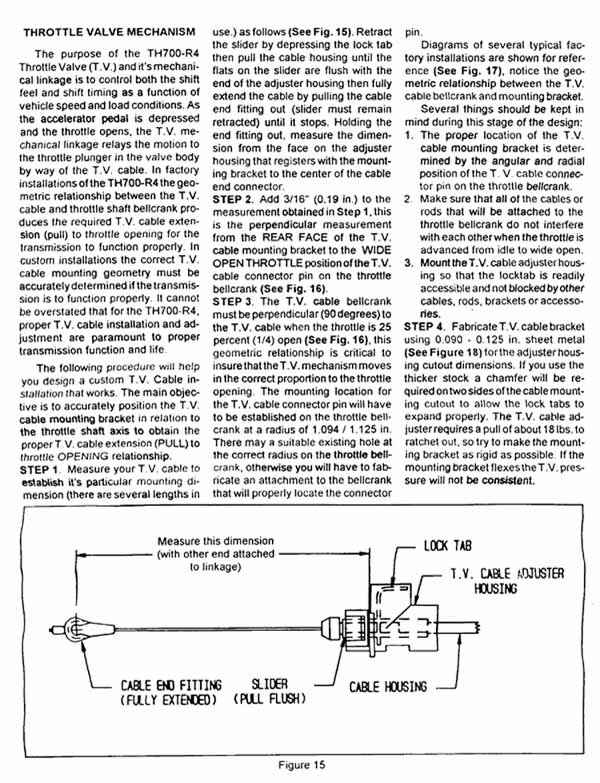
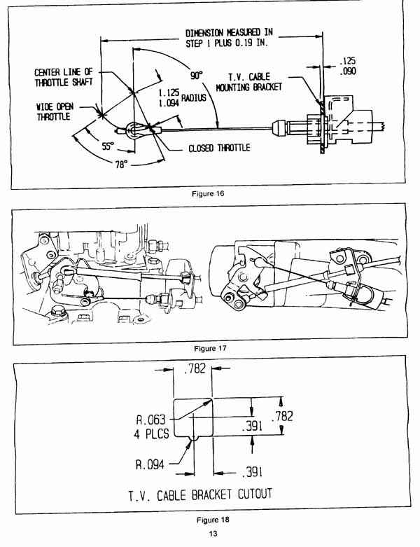
The following drawing shows the geometry for the cable connection to the carb.
These are the critical distances and angles you need to get right so that your transmission will shift properly
and won't be damaged in short order. After this picture I show you examples of how I modified the bell crank to
get these angles and distances. It isn't hard, so don't put it off. I have also added a page that goes into a lot
better detail on how to setup the carb for the TV cable and how to make a mount for the housing end of the TV cable.
Check
this page out for details.
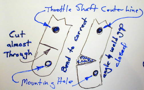
On one of the Q-jets I used there was a mounting hole at the right radius
from the throttle shaft center line, but not at the right angle. I cut almost all the way through the throttle
shaft bell crank above the mounting hole and bent the bell crank to the correct angle and mig welded the gap closed.
I just put a wet rag next to the carb body and welded in a couple short bursts. (see the following picture)
.....................
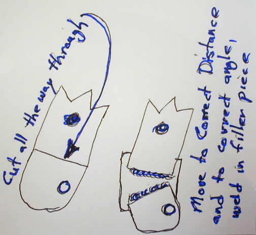
On another Q-Jet I cut the bell crank on the throttle shaft above an existing
mounting hole and below the center line of the shaft. I moved the mounting hole to the correct location and welded
a little filler piece behind the two parts to relocate the mounting hole in the proper position so it was at the
correct radius from the center line and at the correct angle. (see the following picture)
.....................
It only took a few minutes to do this on both of the carbs and needs to be done to make sure you don't ruin your transmission. Some mounting tabs from different sources are now available for different carbs if you
don't feel like doing this yourself.
........................................
For more detailed pictures of how I modified one carb be sure and check this
page ( HERE ).
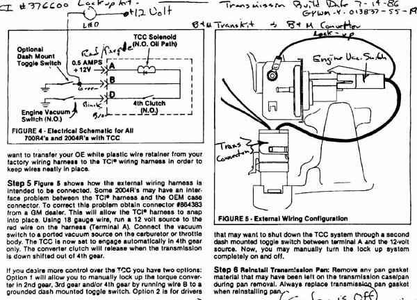
This next image is from the TCI instructions, which is the kit I used to lockup
the converter in 4th and also provides other alternatives to lockup the converter in other gears. Summit sells
the TCI lockup kit (part #376600) for about $77.00. You might be able to scab something together for less, but
the wiring is different in different 700R4's. This kit will help you make sure you get the wiring correct. Money
well spent I feel.
Note: The following wiring diagrams do not necessarily
represent the correct wiring diagram for a "stock" 700R4 as these can vary. These wiring diagrams are
to be used if the 4th (N.O.) electrical pressure switch is in place, such as with the TCI kit.
The following image might be a little hard to make out, but it shows how I
wired in a DPDT center off switch into the wires going to the transmission that control the lock-up for the convertor.
Using the three switch positions as follows: center off position -- never locked; down position -- automatically
locks going into 4th and unlocks on the 4-3 shift; and up position -- manually locked in 2nd, 3rd or 4th.
Note: Look further down the page for Peter Row's wiring diagram on using a SPDT center off switch.
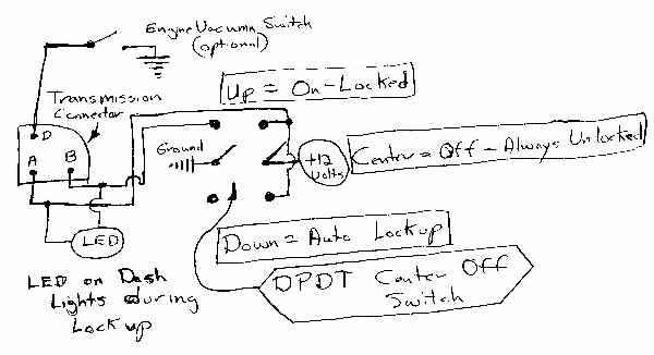
The LED in this wiring mess is in my instrument panel and lights anytime the
convertor is locked. You don't need to have it, just something I wanted. If you don't use the engine (ported) vacuum
switch then the wire from terminal D should be grounded at all times. With the vacuum switch this line is grounded
any time there is vacuum above about 2 to 3 inches.
ADDITIONAL LED WIRING INFORMATION: One side of the LED goes to the 12 volt source for the lockup (wire going to
the A terminal on the transmission). That way if for some reason you don't have 12 volts going to the lockup it
will be a clue as the LED will not light in 4th. If it lights and then you still have no lockup you know the problem
is not no voltage to the lockup solenoid or no ground as if either of these was missing the LED would not light.
The other side of the LED goes to the wire that goes to the B terminal on the transmission. This wire is connected
to ground only when the pressure switch closes going into 4th to lock up the convertor or it will be grounded if
you use a second manual switch attached to the B terminal to manually lock the transmission. When it goes to ground
then the LED lights. Now all of this will only work if you have a kit similar to the TCI kit I'm using that has
a pressure switch that goes into a port that sees pressure only when in 4th and/or you are using a manually operated
switch connected to terminal B on one side and ground on the other side of the switch. I used a radio shack LED
and since it wasn't for 12 volts I run a resistor in series with it to drop the voltage. I'll try and see if I
can find the value of the resistor I used. If you have an LED that works on 12 volts then you don't need the resistor.
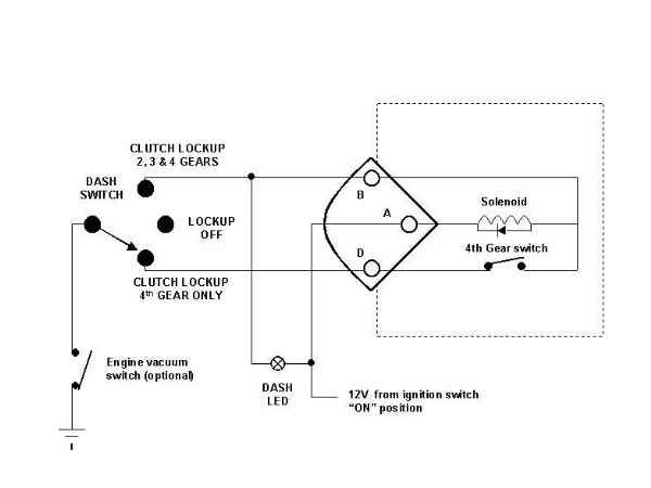
Next is a wiring diagram by Peter Row that looks good to me. This is untested, but I see no reason why it won't
work. This circuit controls everything via the ground side. Mine does this also, but cuts the 12 volts in the center
off position to the clutch. No real reason to cut the 12 volts, so you might want to give this a try. It uses a
SPDT center off switch. Thanks, Peter
.....................
.............................................................................
Next Page of 700R4 info.