On the first page in this section on the 700R4 I showed briefly how I adapted a Q'jet to get the right geometry for the TV cable. Here I will show one I just did in more detail. The bellcranks on these can be different just take the same approach. Also there is no reason this won't work on other carbs including a 3 two setup. Just use this approach on the center carb.......
.
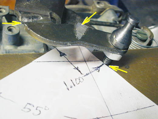
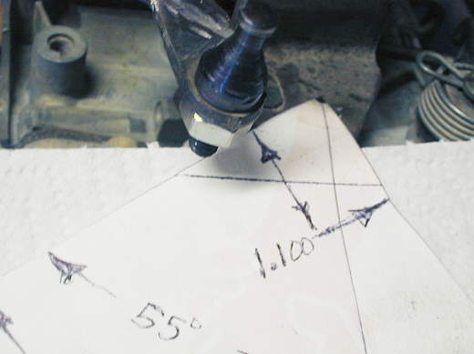
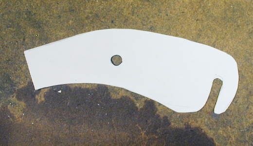
Start by taking a piece of paper and lay out the angles like above. The 1.100 dimension is measured down from the bellcrank centerline (see black dot by top right arrow). This is the distance down from the centerline that the mount for the TV cable should be. It should then be back 23 degrees from vertical. I laid out some horizontal lines on the paper and they should be horizontal to the carb base. Here while I was trying to take the picture they are not horizontal, but at a slight angle. That is not good.
.................. .
.
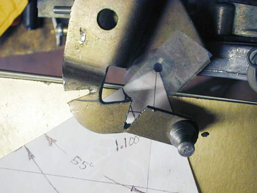
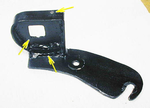
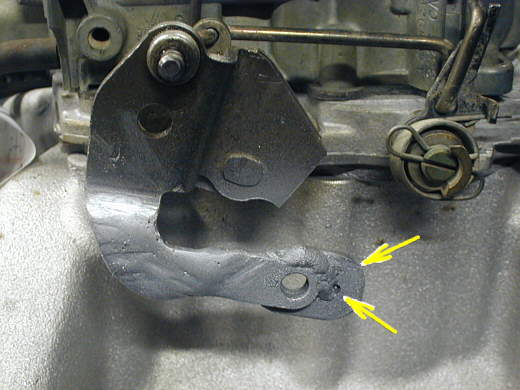
To get the mount point where I wanted it with this bellcrank I cut part way through it with a cutoff wheel in two places. One cut let me rotate it to the right (top left arrow) and the other cut (top right arrow) let me rotate it down to the 1.100 inch mark shown above with the bottom right arrow.
................. .
.
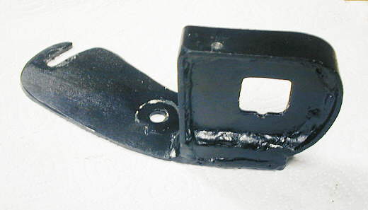
Here I have the paper in the correct position with the vertical line perpendicular to the carb base and the cuts have been spread to get the mount in the correct position.
....................... .
.
Next I took the mig welder on a low setting and welded the gaps in and ground the welds down some. Then I rechecked to make sure the mount was in the proper position.
................... .
.
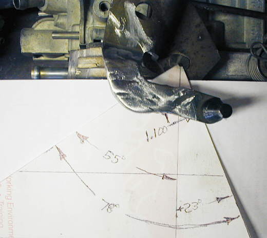
The above pictures show the mount where it would be with the carb at idle (throttle plates closed). Here the carb is at WOT and you can see that the mount traveled the 78 degrees to the other side of the layout pattern just like it is suppose to. If the mount is 1.100 inches down they will do this.
................... .
.
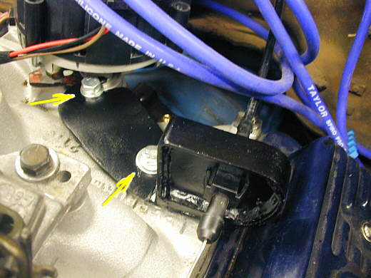
Next I had to make a mount to hold the outer cable end (where you adjust the TV cable). I'm using in this application an Edelbrock Performer manifold for Vortec heads. At the back of the manifold near the distributor there are two threaded mounting lugs that I decided to use. I could have also used the rear carb mount bolts. I made a paper pattern of the bottom of the mount. Since one bolt is under the distributor I slotted that area of the mount so I wouldn't have to move the distributor to put a bolt in and out. Now I just have to loosen the bolt a little and slide the bracket out. I slotted it so that the pull on the bracket wants to pull the bracket into the bolt.
................... .
.
You can see the slotted part of the bracket by the bolt near the upper left arrow. The other bolt just mounts into the other hole.
................... .
.
Once I had the bottom piece cut I took a piece of 12 gauge steel (about .100 inch thick) and milled the opening in it where the TV cable end mounts (middle left arrow). The dimensions for the hole is on an earlier page. I used the mill, but you could use a drill/saber saw/ files or whatever works for you. I used a piece of 1/2 inch square tubing (bottom arrow) to move the mount up so that the finished cable would be a horizontal pull to the carb. I then used a piece of .120 X 3/4 inch strap (top arrow) to wrap around the 12 gauge to stiffen the whole thing up. The TV cable does exert a pull on the bracket so don't make it to flimsy.
................... .
.
Another view. The small hole in the top is for the return springs for the carb.
................... .
.
I welded a small tab (top arrow) with a hole in it (bottom arrow) to the bellcrank that was modified above so I could hook the return springs to the bellcrank.
................... .
.
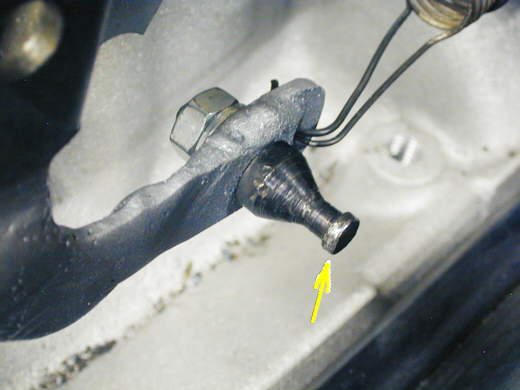
The arrow points to the attachment point for the TV cable. In the past I've used a piece off of the carb for this, but for this one I made this from a piece of 1/2 inch round cold rolled steel in the lathe. I turned the right side in such a way that the TV cable can mount to it and turned the left side down to 1/4 inch and threaded it.
................... .
.
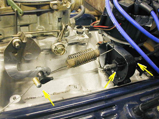
This time I used a universal TV cable that has a stop (left arrow). This meant that the location of the bracket to the right (middle arrow) is not critical. If you use a stock TV cable go back to the first page in this section to see where the bracket has to be located. This cable doesn't go in and out by clicks, but screws in and out for adjustment where the right arrow is. You can't really see the adjustment part, but it is there. Notice that the cable is pulling straight and not setup at an angle.
................... .
.
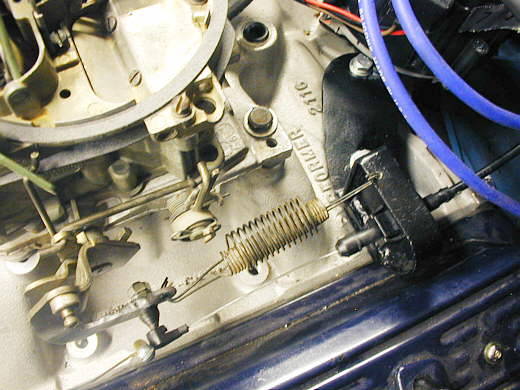
A top view of the setup.
................... .
.
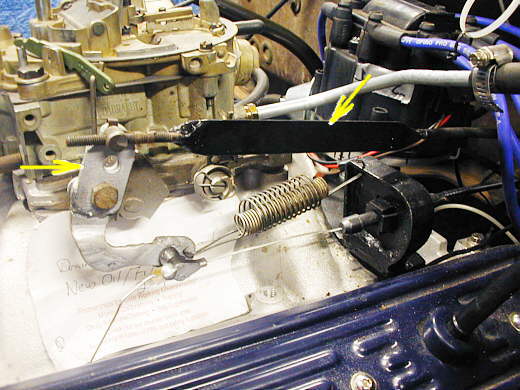
I added a tab (left arrow) to the top of the bellcrank to hook the mechanical throttle linkage (right arrow) that was in the Ford pickup that this small block chevy went into. The tab is welded to the bellcrank right below the left arrow.
This looks complicate maybe, but goes pretty fast and in an hour our two you will be done and your TV cable will be setup properly and your transmission will live a long happy life. If you don't do this you will soon be looking for another 700R4 or will be saying they are a crappie transmission when they aren't.
For the final adjustment go back to the first page in this section and re-read it again.
c ya,
Sum
.............................................Next Page of 700R4 info.
............................................ Return to Tech Info Page