..................
........--- Dan Nease's 26 D Rudder Construction ---
..............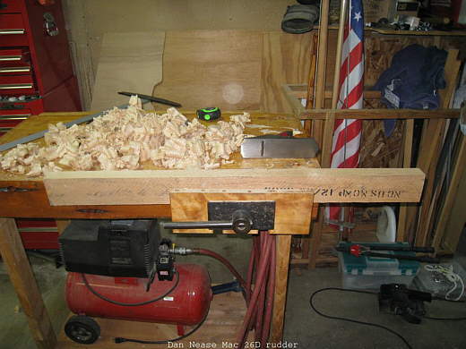
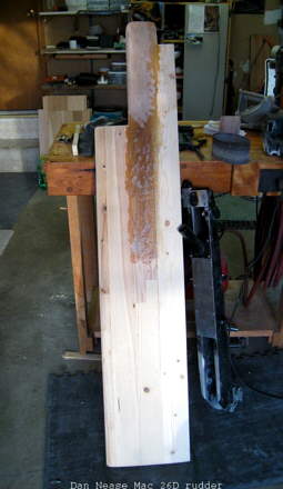
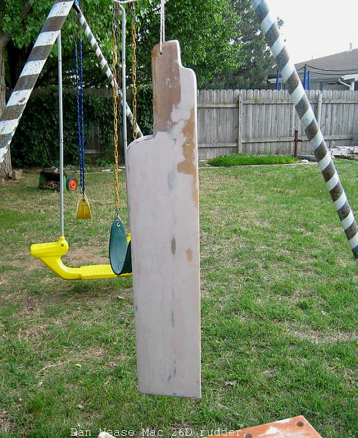
This is the base stock and the heart of this whole rudder. It is actually recycled Oak from a shipping pallet, what makes it exceptional is that it is perfectly quarter sawn. This is the grain orientation that I wanted, to handle the most bending force which it would be subjected to on the boat and to ease the drill bit wander when I drilled the pivot hole. In this picture the grain runs perpendicular to the sides of the blade, or vertically, so when I drilled the pivot hole it would also be perpendicular with the growth rings. The pivot hole is not inserted with any metal sleeve just polyester resin coated to shed water absorption. This piece is obviously to short for the completed rudder (63 1/2 overall), so I had to glue up the rest, even the end grain on this board.
..............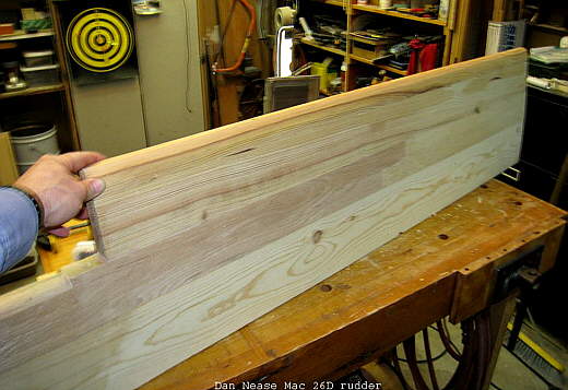
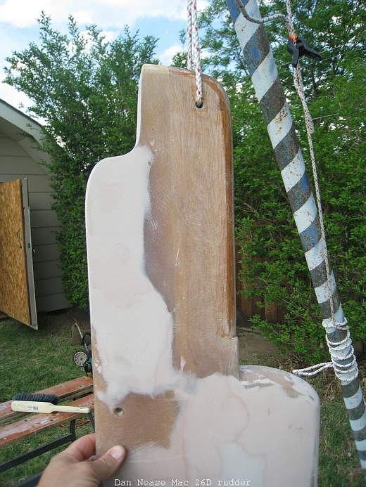
This is the completed glue up and the beginnings of the bullnose leading edge. The trailing edge here is full thickness and had to be planed down to a nice gradual taper, (which we'll see later). The glue up here is a standard procedure using "Gorilla Glue" with the use of hardwood dowels from the Oak forward (up in the pic). The end of the Oak is scarfed in an "L" shape and doweled to lengthen it as needed. All other wood in the rudder is Douglas Fir and quarter sawn as best as I could find, Douglas planes easy and glues up nicely with good hardness. From the Oak rearward there are no dowels, just glued and clamped. Clamping Gorilla is best done by wetting the glued edge with water a couple of times prior to gluing, clamping should be at least 24 hr for a full cure (don't rush this part). Also you'll see under my left hand the start of the radius which will fit into the Aluminum rudder castle, this was final shaped with a belt sander to fit snugly against the inside radius of the castle. This design was also superior because this gave me a full 13" of vertical rudder inside the castle (which is prone to flexing or twisting) this makes the whole castle much stiffer.
..............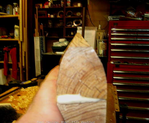
Here is the end grain of the leading edge which shows the glue squeeze and the grain orientation, the thickness here in just about 1 5/8, by the time all the fiberglass is in place it totals a little over 2".
..............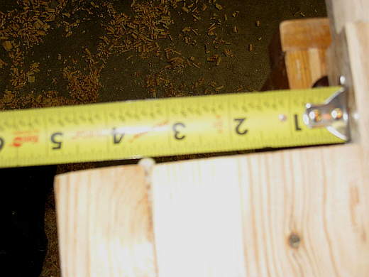
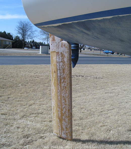
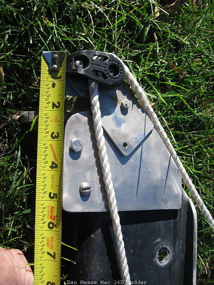
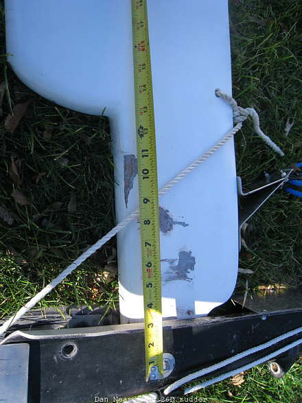
Here is the rough leading edge distance, the surface on the "dumb" end of the tape faces forward and is just below the bottom pintle and just below the painted water line ............
..............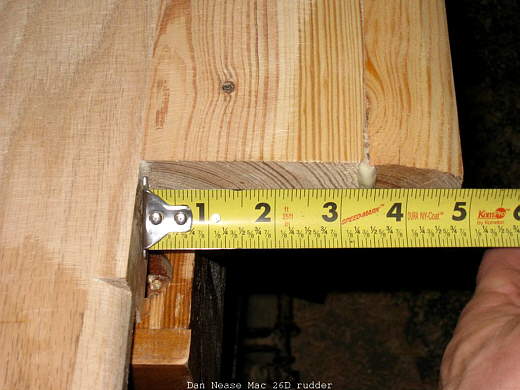
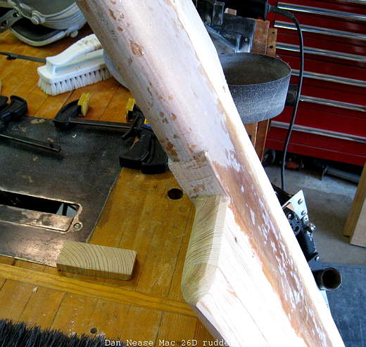
......... I left this surface square with just a little rounding for the strength as this is the Oak, plus I didn't want it to close to the transom.
..............
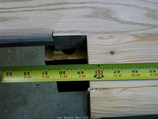
This photo shows the rough length from this transition area to the top of the blade which is in the castle. It was later cut down to around 13" and heavily radiused to make the "swing" as it is raised and would contact the inside of the castle if left square. Remember the Oak is what is inside of the castle for it's desired strength.
..............
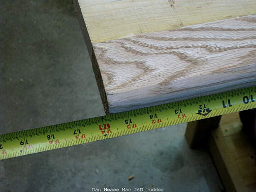
This picture is the rough length to the bottom of the blade 48 1/2" before the bottom gets radiused.
..............
Here is the start of the Polyester Resin and fiberglass cloth. I used both biaxial and shredded cloth which you can buy at Home Depot. At this point in the construction I wanted two things to happen, (1) strengthening of the ruder (2) Getting the thickness heavy in the middle with tapering to both ends, yet covering enough to resist damage from debris. The biaxial cloth I used close to the wood so when I sanded the shape I wouldn't sand through the cloth and loose my strength. I actually used more shredded cloth and overlapped vertically down the length of the blade. All in all I used about a gallon of resin, there is waste when you sand to shape and at this stage I wasn't concerned with smoothness. You can also begin to see the size of this blade as compared to the castle. This was planned as my old HDPE blade would easily let go around 20-25 degrees of heel rounding the boat into the wind. That blade had about 32" in the water and this time I wanted extra depth, my thinking was that if it was to long I'd just cut it off and re-glass to seal it back up. As of the end of 2009 season I haven't cut it off yet.
..............
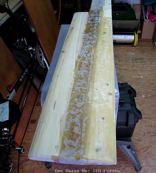
This view is looking down the length of the blade and you can see how I layered the fiberglass starting in the middle first, this was to get to the rough thickness and then smooth into the leading and trailing edges. Make sure you make it to thick to go into the castle as you can sand it smooth later and not have a porous surface. Also notice the trailing edge which I started tapering, I used a draw knife and my belt sander as a lot of stock needs to be removed.
..............
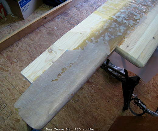
Here is more glassing and I'm moving towards the back, each pass takes roughly 8 oz of mixed resin and I did one side each night in my climate controlled shed. Then flip the entire rudder over and do the same thing to the other side the next night. Also notice the radiused bottom nice and round, I didn't want a flat surface as that could turn into a planning surface if the conditions were right and possibly give me a fight in the tiller handle.
The trailing edge came together as I overlapped each side around the back, later on I stood it on edge and taped down the length and filled the trailing edge full of resin to be later sanded square and straight.
..............
More glassing and a better detail of the trailing edge and the transition into behind the castle, which I wanted full thickness as I needed a up-haul bracket to mount in that area. To complete the glassing process I just kept adding mat and resin until I had the thickness to where it should be. Sometimes in between coats I belt sanded just to level off any unevenness, that's up to you.
..............
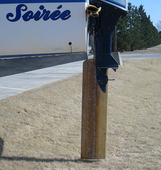
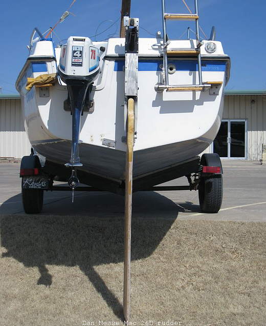
Here is my first test mount which I had to do in my Church parking lot ditch. As you can see this baby is long and massive. Notice the top edge where it just touches the transom by a hair, this only happens in the center position and I wanted it close for smooth water flow.
..............
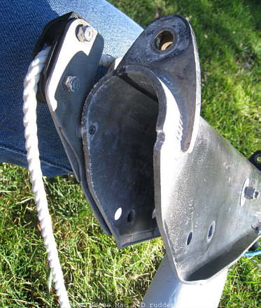
This and the next picture shows greater detail of the pintles, transom and blade...............
..............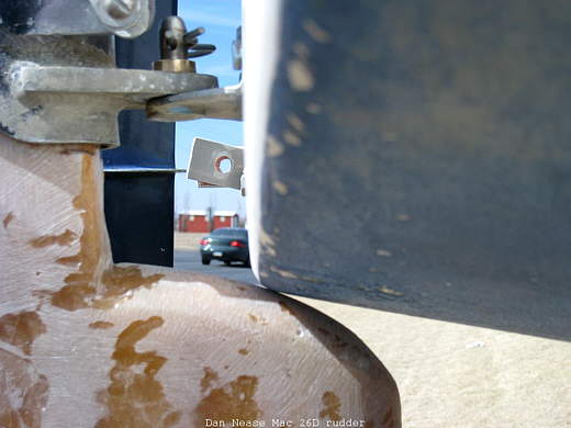
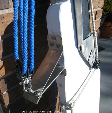
............Notice the brass bushing inserted into the Aluminum castle, both top and bottom are done and there is NO play at all in the whole assembly. I used a tapered reamer for the I.D. of the castle on the top bushing leaving it tight for an interference fit which had to be pressed in a vice. The bottom bushing was reamed likewise but left just slightly looser allowing for centering movement and when assembled with sleeve locktight (green) overnight set up for a perfect fit. In the top of the picture you can just see the downhaul turning block, this would later be relocated and reinforced as this rudder floats very well and needs some pull to get it down in the water.
..............
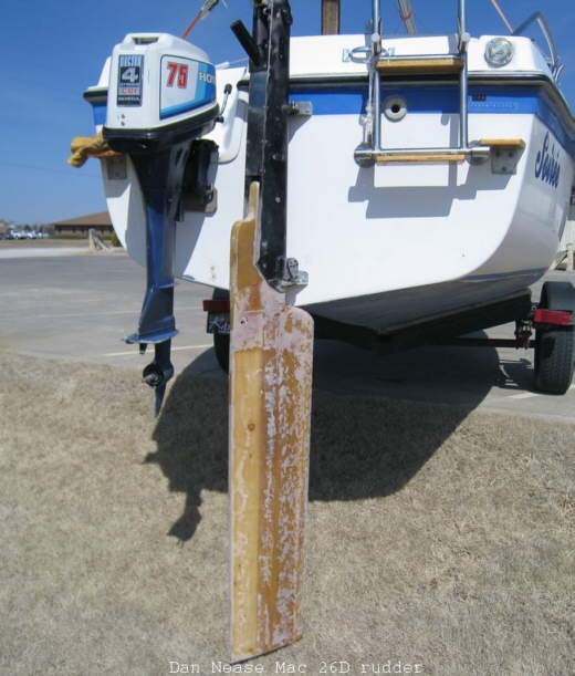
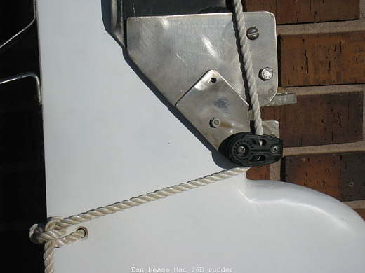
Here we see the complete rudder assembly except for the control lines. Notice that the castle has a stainless steel stiffener plate bolted to the back edge, this plate is an excellent mod and easy to do requiring only 8 holes to be drilled and thru bolted. Above the plate is my bracket for Old Glory which is welded steel primed and painted black, this to is also a stiffening device. The up haul control lines run on either side of the flag bracket and the down haul line runs down the Starboard side and up the tiller. Look very closely and you can see the new pivot bolt location 13" up from the bottom of the castle, this allows the Oak stock to be the stiffener for the bottom of the castle (you can see the bolt on the left side). Now the whole rudder castle is supported against twisting and flexing, this is a great improvement over the stock design. On the top center is my Harken 29mm Carbo cheek block, and left of that is a bullseye fairlead mounted on a bracket to guide the up haul 90 degrees down the tiller handle. The up haul has a 4:1 purchase.
..............
This and the next picture shows in better detail the trailing edge taper and the drilled hole for the down haul...........
..............
............. Remember the two drilled holes need sealing with resin and probably should get a maintenance coat with a "Q" tip every year.
..............
Here is the final process before painting. I used Bondo to fair smooth the entire surface for a clean and smooth finish. Don't spend alot of time smoothing out the fiberglass, that's for the structural shaping, here is where you can focus on the finish.
..............
Notice up in the castle area that I didn't use the Bondo where the Oak goes inside the castle, that area has fiberglass only since the Bondo could chip out and cause play to develop later. Also the top radius since this picture has been modified (rounded more which allows for a full 90 degrees raised position).
..............
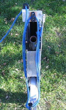
Here is the assembly bolted together showcasing the down haul system. This is a 2:1 purchase and works quite nicely, on the top of the castle is another fairlead guiding the line forward to a jam cleat which is mounted on a hinge to "flip" up when pulled to hard releasing the line. This is my safety device should I hit ground or whatever. The cheek block location is as low as I can get it, this allows for a straight pull forward on the blade and lines up the rope for a 90 degree pull. The stainless plate bolts into the original holes and allows the block to be mounted lower, it also has two layers for strength and a blind fastener countersunk from the inside of the castle. The cheek block is a Harken 29mm Carbo which has the one end tapering and rounded, this is significant to allow for clearance when turned all the way (boat to Starboard). This also shows the new pivot bolt location as compared to the old one, this adds great strength which means better feel in the water.
..............
.................
..............
......................
..............
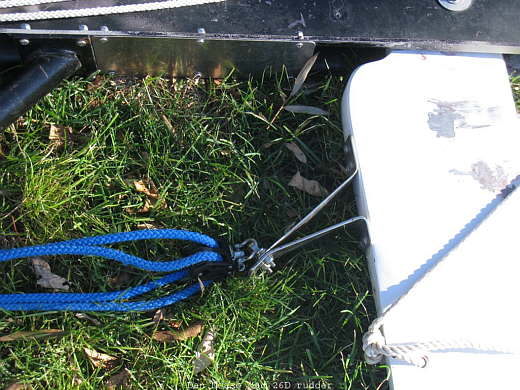
In the rest of these photos you can see different details of the up and down haul systems. When I travel I have all three pieces separate (blade castle and tiller), two 3/8 bolts and hang it on the pintles, pull the up haul and your ready to go. Some final considerations: 1) keep with a 4:1 uphaul, this blade is heavy and needs alot more on land to lift than you might imagine, also the uphaul bracket needs to be out from the trailing edge to give enough angle so when you lift the blade you're not just pulling vertical. 2) The up haul has a Harken 350 cam cleat mounted on the tiller handle just over the rear hatch, this makes the line easy and fast to cleat and release and can be done from the rear seated position. 3) As a safety factor whenever you fasten something any where on the boat (unless it is nonessential) always use through bolts and lock nuts, the last thing you want in 40 mph wind is a failed screw when it should have been bolted.
..............
...................
..............
...............
..............
.....................
..............
Anymore questions and comments can be sent to me via email at dnease26(at)yahoo(dot)com