..........................Endeavour Index Page............Plumbing Mods Index Page
..................................Previous
Page..............................
Next
Page If There Is One
===========================================================
............................................--- 3 Bilge Pumps -- Part I ---
===========================================================
I mentioned on an earlier page about the new water tanks that when we first got the boat we cot water in the bilge, lots of it, from a leaking water tank. The bilge pump came on but didn't pump it out. We were ready to take the boat from Ft. Myers Beach up to a yard off Charlotte Harbor. I had to get a taxi ride to a West Marine and picked up another pump. I didn't attach it to the bilge discharge line, but instead to a temporary line that the previous owner had on the boat. With that we pumped into a 5 gallon bucket and hauled the water out.
In the yard the next spring (2012) I pulled the pump and figured out where the lines go and tried to think of something that would work better. I started to wonder if the first pump was actually bad, as it did come on, or maybe there was something wrong with the discharge lines. The line is really long going all the way back to the stern where it goes to the top of the transom and then back down a bit and out a rather small thru-hull above the water line. From the bottom of the bilge to the high spot is probably almost 6 feet of head. So the pump is trying to pump through a pretty small hose over a long distance with a fair amount of head.
I'll be stuck with the head but plan on replacing as much of the discharge run as I can with 1 inch PVC which should cut down on the restriction a fair amount.
..............
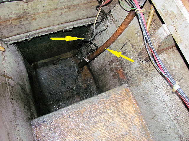
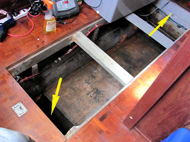
If you don't have an Endeavour 37 above is the bilge on the boat, or at least the primary part of the bilge. The area under the 2 X 4's is where the 90+ gallon leaking tank was and where the new four 20 gallon tanks will reside. Below that area is the keel and is also the area of the keel that is filled with 8000 lbs. of lead.
The left arrow points to the deep part of the bilge which is also part of the keel and just looking at the outside of the boat you can't tell where the lead ends, but by tapping on the keel you can tell from the sound.
..............
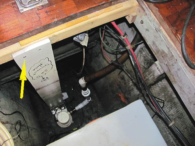
Now you are looking down into the deep part of the keel. The right arrow points to the old discharge hose and the left arrow points to the wiring for the bilge pump. Just aft of the top arrow is the fuel tank that I think is about 50 gallons and which we also will probably replace.
..............
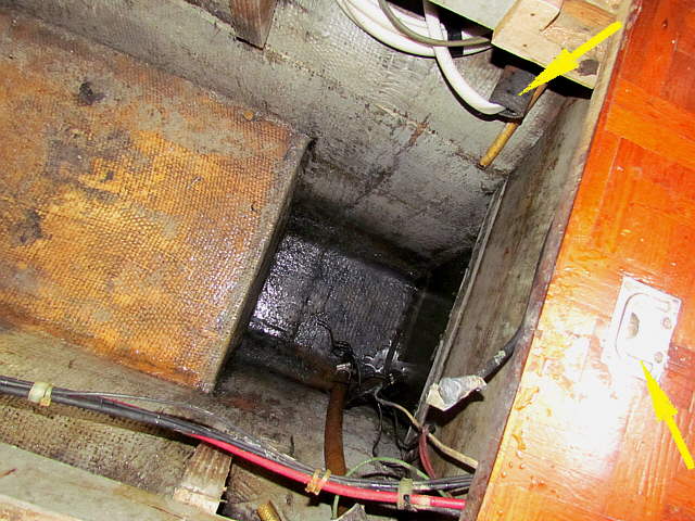
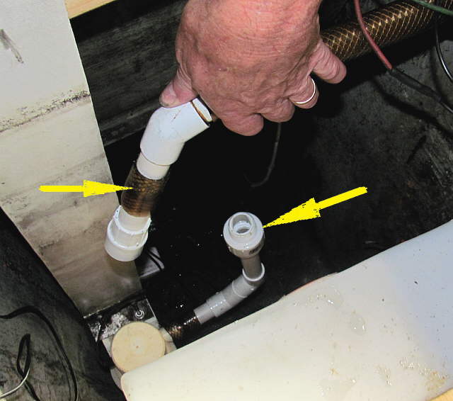
Another look down into the deep section where the bilge pumps will go. The right arrow points to the latch that you use to pick up the part of the sole that is over the fuel tank and under the companionway. The top arrow points to the supply line from a deck plate that went to the water tank. I'd put a hose down it to use instead so that we had a pressure feed to the tank and not gravity.
..............
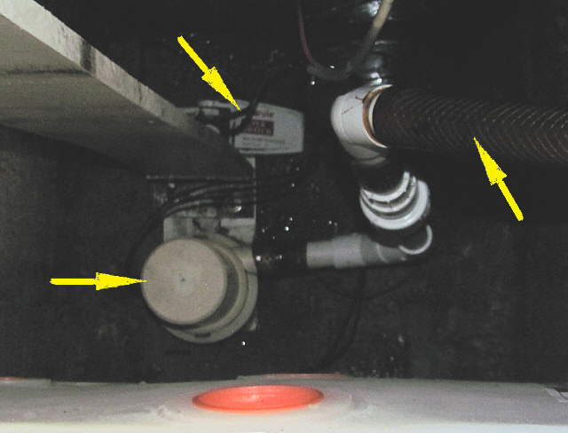
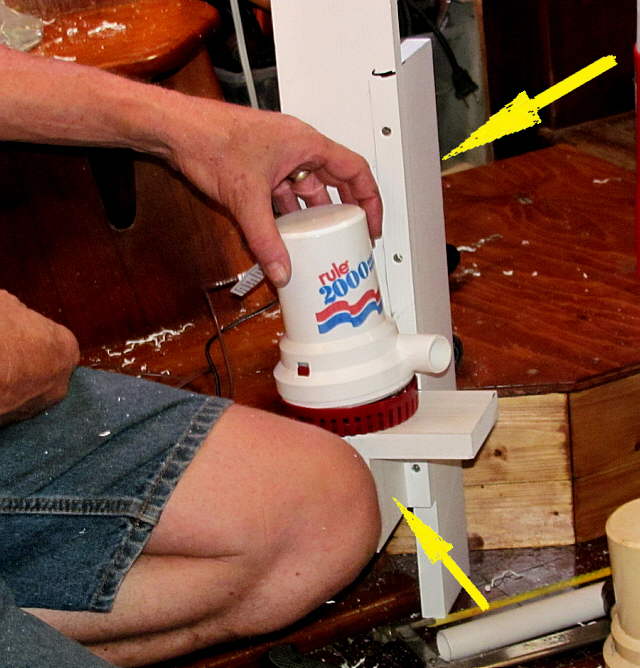
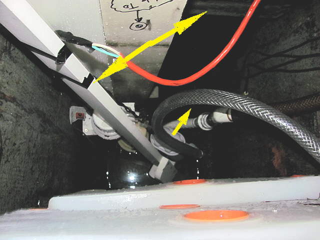
Sorry about the quality of the pictures to come. There was one pump (Rule 2000) already in the boat and it was attached to the white PVC board, left arrow, and the float switch is mounted to the back side of the board, top arrow. The right arrow points to the old discharge hose that was attached directly to the pump. The white PVC fittings are new.
..............
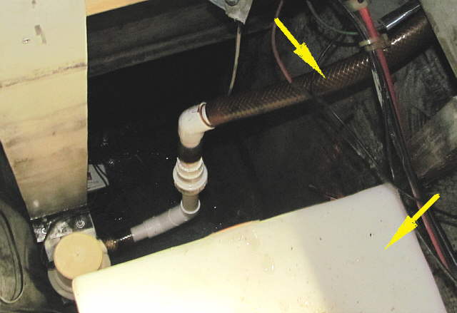
The bottom right arrow points to one of the new 20 gallon tanks (total of 4) that will be for the main water supply. I replace some of the hose from the pump up with PVC pipe and fittings and will replace as much of the rest of the line to the stern of the boat as possible with 1 inch PVC.
..............
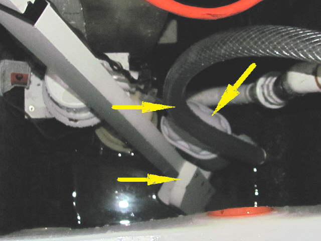
The one fitting, right arrow, allows the line to be disconnected from the pump which will make it much easier to remove the pump for service if needed. I will still use short sections of hose, left arrow, at some points with hose clamps, still to be installed. By loosening the hose clamps I can turn the fitting and separate it. The bottom hose will allow the PVC to be attached to the pump.
..............
The pump mount board is attached to a cross-member with a couple screws. To the right about where the discharge hose disappears under the cabin sole is where the run of 1 inch PVC pipe will start to the stern.
..............
With one pump in place next up was adding a second pump above the first one. Again PVC wood from Home Depot was used. I added pieces at the bottom and back side to help support the pump and the float switch, arrows. The switch is out of view on a platform on the opposite side of the pump.
..............
Again the float switch is on the back side, arrow. The board that supports this pump is located next to the other pump. The plumbing for it will be similar to the bottom pump and will run also to the stern of the boat.
There is a manual pump also on the boat by the helm, but I can't imagine having to pump it during and emergency, but we will keep it. The pickup for that pump is down behind the fuel tank out of sight in these pictures.
..............
Above you can see both Rule 2000 pumps in place and the water tank there also. The picture angle makes it look like the water tank is a ways out and over the deeper section, but that is not the case.
The bottom arrow points at the hatch cover for this section.
..............
Before we left the boat we installed a third pump. It is a Rule 500 automatic pump. The purpose of this pump is to keep mostly any rain water that ends up in the bilge out while we are gone. We think we got most of those leaks fixed before we did leave. We might also plump this into possibly the sink line and depend on it for any small bilge water problems and count on the other two pumps to be the emergency back up pumps.
It again was mounted to a piece of the PVC lumber and...
..............
.... after the picture was taken it was place over next to the other two pumps as shown by the arrows. You can see some water we put into the bilge to test the pump. The auto on/off feature results in the pump coming on when the water level goes up a couple inches. Then it shuts off when the water is down at the strainer. I think that it does this so that if there is considerable water in the discharge line and it drains back when the pump goes off that it doesn't cycle on and off. The return water doesn't raise the water level enough for it to go back on.
We took the line from that pump forward and out one of the thru-hull holes that was minus a thru-hull at this time. We will have to take it someplace else if we decide to keep it in the bilge along with the others.
One option is to just use it in the yard up on stands and run the line to a sink when we are gone. I'll finish posting about this when we return to the boat and run the discharge lines and wiring/switches.
When we left the boat we left one of the six 80 watt solar panels hooked up and had it connected to the charge controller and from the controller to one battery. The single small bilge pump was connected to the battery with everything else on the boat disconnected.
===========================================================
.................................................................................. Next Page If There Is One