.......................................Endeavour Index Page.................Interior Mods Index Page
....................................................Previous
Page..............................
Next
Page If There Is One
===================================================.................
...........................................--- Boat Fridge Install on the Boat Part IV ---
===================================================..............
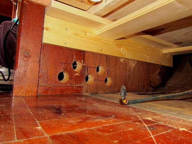
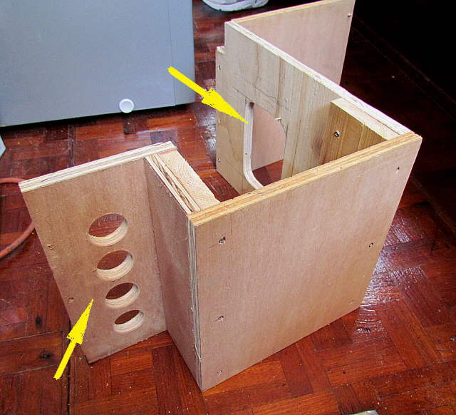
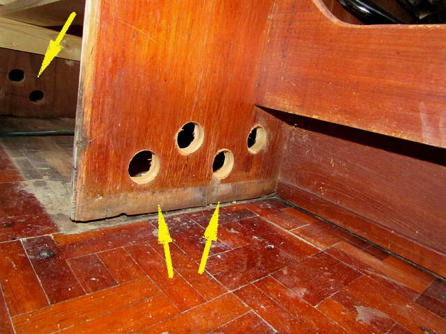
The last item to be taken care of was installing the compressor/condenser and hooking them to the evaporator in the box. I wanted to ventilate the area where the compressor was as well as I could. I drilled the holes above, bottom arrows, with a hole saw into the bottom side wall that is next to the stove.
Opposite them, top arrows, I put more holes....
..............
... into the bulkhead by the post. These holes go into the area under the starboard settee. There is a storage drawer in there, but some distance in from the holes. That ought to be a cooler area since the hull would normally be down in the water. Also the hull is off on the right side of this area in the picture. You can see the bottom of the fridge above. The wire was the 12 volt wire from the previous fridge that we used with this one.
One thing that determined the depth of the fridge was I had to leave enough room under it for the compressor. The other is that it couldn't get so deep that it would be hard to reach the bottom for either of us.
..............
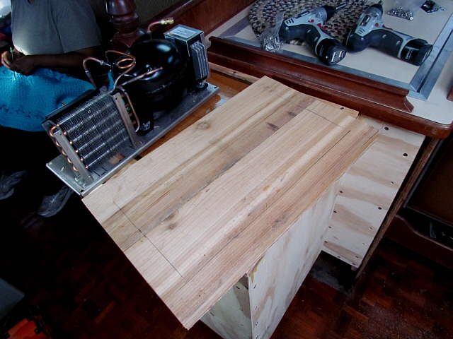
The compressor/condenser ( refereed to as the C/C hence forth) could of been bolted directly to the sole under the fridge, but the platform above was made for it so that it could be serviced a little easier and for one other reason shown below.
It was made from two lengths of cedar wood ....
..............
.... screwed to a piece of plywood.
..............
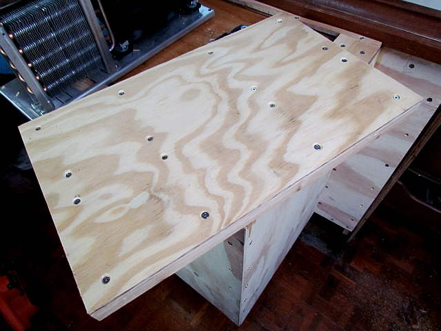
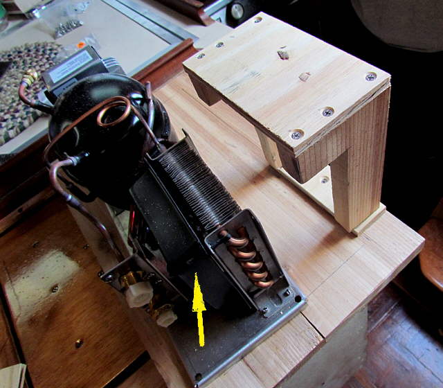
It also make it easier to construct a shroud for around...
..............
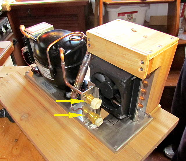
.... the condenser coil to the right of the arrow. The unit came with a shroud around the fan, arrow. The shrouds make the unit much more efficient as they help to make sure most all of the air from the fan goes through the cooling coils.
..............
Also the shroud I made will get the air out from under the fridge and into the galley area.
..............
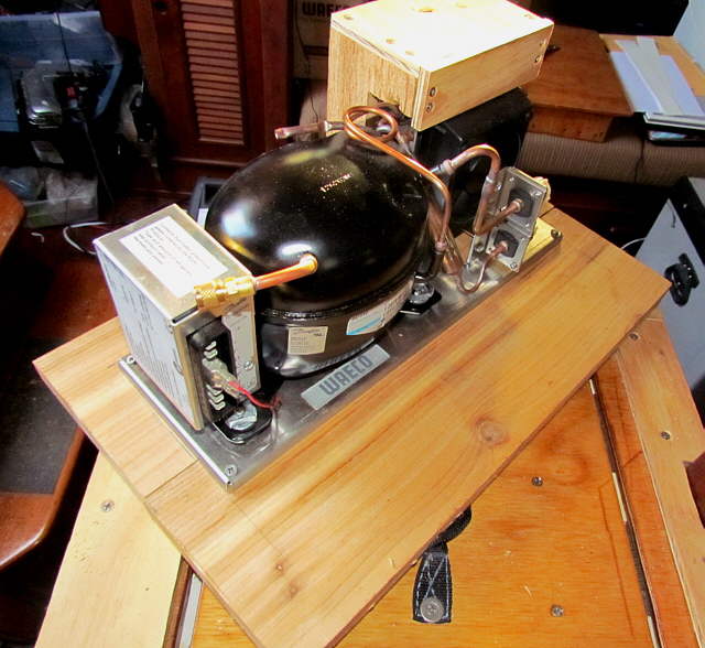
The C/C is actually quite small. The model we chose has a horizontal 'Long Base' layout and is 5" D x 15" W x 6" H. They also have a couple other layouts to choose from. I personally felt this layout was the most efficient with the condenser off to the side, but that might not be true. Also we didn't want it to be high. I'd look for the one that fits your application the best.
..............
These are very good units and it seems that a lot of different manufactures of fridge units all use the Danfoss compressors. The main difference is that some shroud the condenser better than others and I tried to do that also.
..............
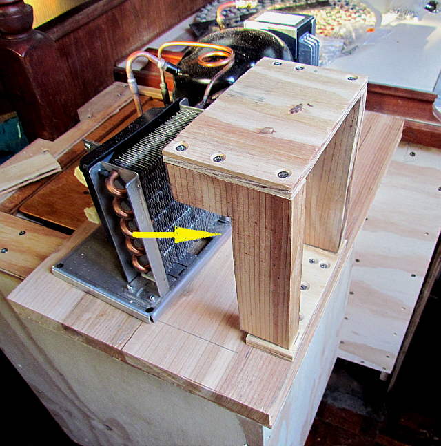
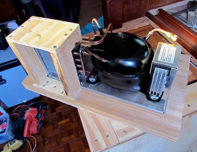
The arrows above point to where the coolant line from the evaporator attaches. It is a single line down out of the box, but at the end it becomes two lines where it attaches here. The ends are different sizes so you can only attach them one way.
The evaporator and lines are pre-charged and when you attach them to the fitting above there is a seal that opens and then the system as a whole is charged. Tighten the fittings to the torque they recommend in the tight space is a little challenging. I guessed that I had them right and the system worked fine for a couple months. The test will be when we go back and start it up.
Above is also a better shot of the fan and its shroud.
..............
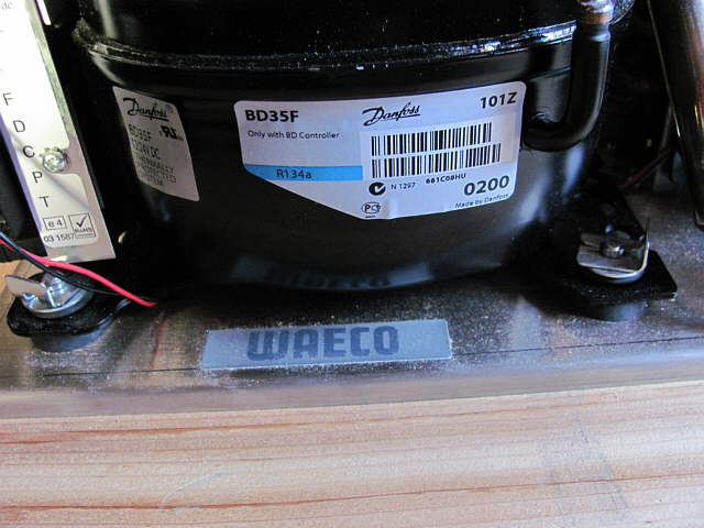
Note the 'BD35F' above. The denotes that this is somewhat more efficient and better suited to warm water and bigger boxes than the 'BD35' without the 'F'. Spend a little more and get the BD35F. If you have higher cooling/freezing needs then you might have to step up to one of the 80 series compressors. I'd considered that, but I'm glad that we didn't. The one we got with all of the insulation is easily up to the job.
One final note and that is if you are going to be cruising in really hot tropical climates with warm/hot water you might want to consider a water cooled unit vs. the air cooled like these, but that requires a thru-hull. There again we did not need this as we won't be in those climates with the boat.
..............
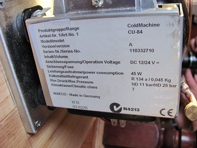
Above is the data attached to the unit. I haven't gotten a good amp reading with the unit the way the current boat wiring is, but with the 45 W claimed I feel that it is very close to that once it is on for a few seconds and running.
..............
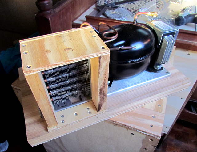
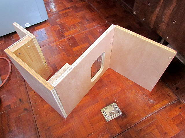
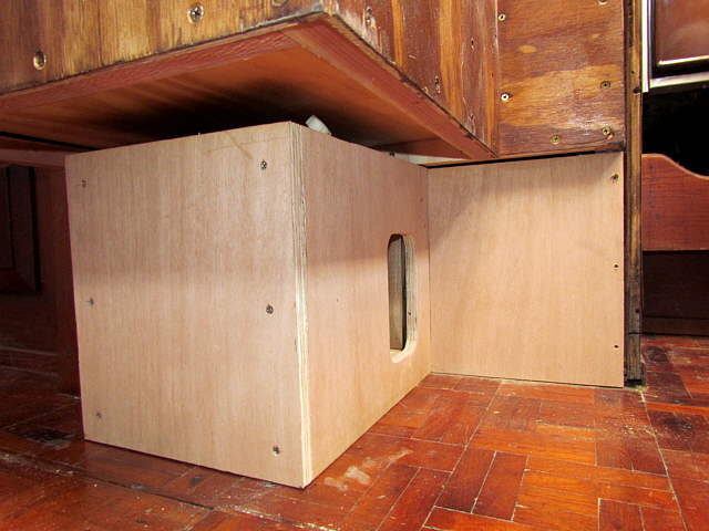
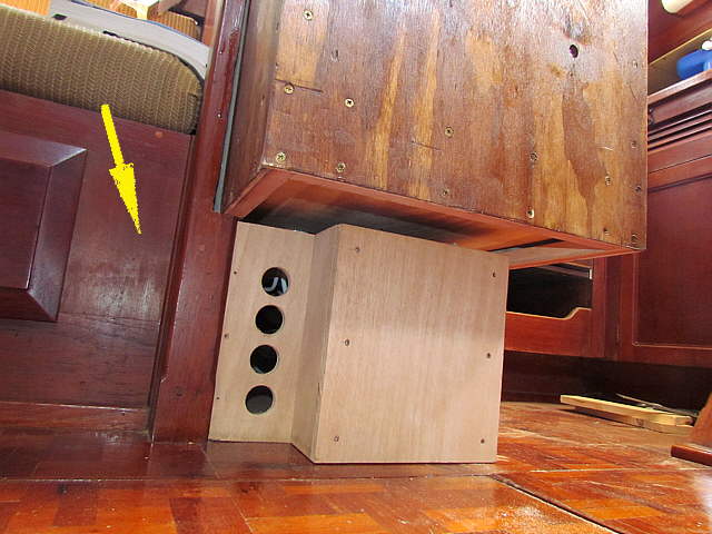
The enclosure above was made to finish off the install. The window is for the outlet for the condenser cooling air and the shroud butts up against that opening.
..............
The holes on the left are yet another opening for air to enter or escape from the C/C area under the box.
..............
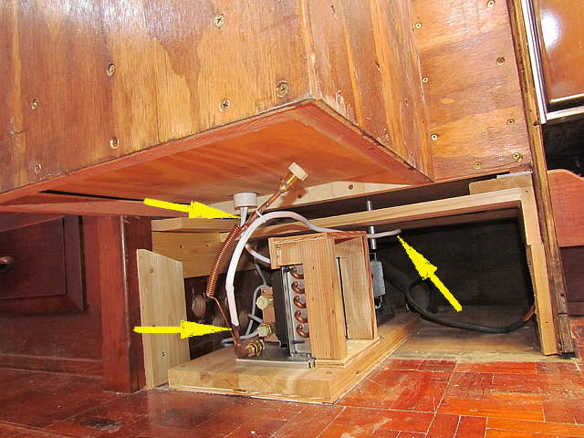
Here the C/C platform is mocked into place. The nice thing about the platform is that you can slide the unit out to attach the coolant fittings, bottom left arrow. The upper left arrow points to the coolant line exiting the bottom on the box via the PVC pipe along with the wiring going up to the thermostat.
The coolant line is about 6 feet long and I looped it back behind the C/C, right arrow, and then forward to the fittings on the C/C.
..............
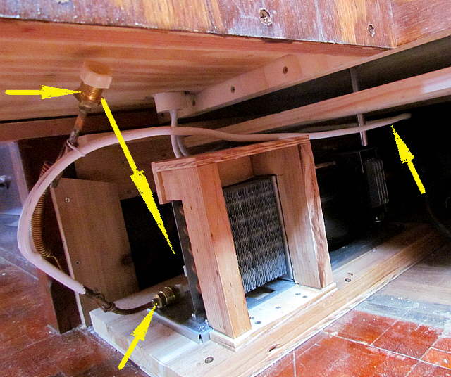
The bottom arrow points to one of the lines that has been connected. If you look to the left of it you can see where the second line comes away from the coolant line and goes to the fitting by the upper left arrow. The long arrow points down to where that fitting was also attached to the C/C.
..............
Once the lines were attached the platform was pushed into place and screwed to the sole of the cabin and the bottom enclosure slid in against it and the opening. Note that the top of the enclosure also has an air space above it for hot air to escape. You can't see this gap unless you are laying down on the floor.
..............
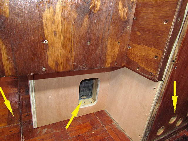
The arrow points to the drawer under the settee behind which is another set of ventilation holes. You don't want heat to build from the C/C area under the box if you can avoid it. That will help make the C/C more efficient and help to keep the exterior of the box cooler.
..............
Right arrow points to more ventilation holes. The middle arrow points to the air duct expelling hot condenser air. The left arrow points to the removable sole sections that allows access to the bilge area. They clear the bottom enclosure and the box above them so can still be easily opened if needed.
===================================================.................................................................................. Next Page If There Is One