.......................................Return to Sumner's Home Page
Previous Page...............B'ville Car Index Page.........................Next Page
.......................................T--- THE REAR ---
On Legend and Dwarf cars they turn the motorcycle engine sideways and put an adapter on the output shaft from the transmission where the drive sprocket normally goes. This is hooked to a drive shaft that normally drives a Toyota rearend. This allows them to have suspension, which I want.
A few years back the salt wasn't very good and some of the cars with no suspension couldn't run because, either the car miss-handled, or it jarred the driver's head around so much that he couldn't see. Some of the people who ran solid suspension told me that if they were building their car from scratch they would incorporate some form of limited suspension and highly recommended to me to do the same on both ends of the car. The salt is hard and smooth most times now, but who knows what it might be like in the future. ( More thoughts on why I'm going to all of this trouble for suspension )
The Legend people have had a ring and pinion made for the Toyota rear that is a 2.50 : 1. That might have worked for me, but I didn't like the option of only one "high" rearend ratio available as all of the other ratios were in the range of about 3.20's to 4.10's., good for circle track racing, but not B'ville.
The solution I feel for me is to try and use the normal chain drive from the motor back to a jack-shaft, since I could then change front and rear sprockets for relatively cheap gearing changes (a poor man's quick-change). The problem with this was I would need to run a fixed rearend with no suspension since I would loose chain alignment if the jack-shaft (axle) was to move up and down on the ends during suspension travel.
I'm going to try and overcome the problem of a fixed jack-shaft by using parts from a rearend out of a Datsun 280Z (at first I thought this rear was from a 240, but now I believe it is from a 280Z) with Independent Rear Suspension (IRS). Follow along and see if this makes any sense.
.........................
 .
.
.
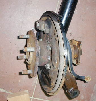
Here is the outside hubs, bearing assembly, and short shafts that hook onto the 1/2 shaft at the right of the assembly along with the brake backing plate. The tube going off the picture to the top is the strut assembly.
I am going to make a new housing to hold the bearings and will also use the hub and short shaft. I won't be using the brake parts as I'll have a single disc brake on the center section.
The hub assemblies will be attached to an axle like beam similar to what was
used on Alfa Romeo's, Aston Martin, Lotus, and some other cars. They used a live axle that could move on the cars
suspension, but this axle went around behind the fixed center section. They used 1/2 shafts from the fixed center
section to the "floater type" hubs attached to the solid axle. This will make more sense when I get to
the suspension layout page.. By the way this type of suspension is call "deDion" (thanks Roy for that info)
and you can find out a little more about it on this web site and also see a picture of it there.
 .
.
.
.
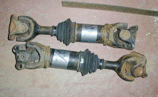
These are the stock Datsun half shafts and they will be use in stock form with new U-joints.
.
.
..
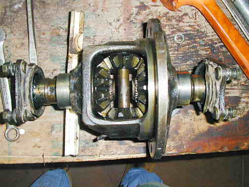
 .Now things will get more confusing. This is the center
section from a Datsun 280Z differential, similar to a Ford or GM except smaller. Notice the main side gears that
the whole assembly turns on while the car is going "straight". The axle shafts go into this center section
from the ends and also turn with the assembly at the same speed as the assembly while going "straight".
.Now things will get more confusing. This is the center
section from a Datsun 280Z differential, similar to a Ford or GM except smaller. Notice the main side gears that
the whole assembly turns on while the car is going "straight". The axle shafts go into this center section
from the ends and also turn with the assembly at the same speed as the assembly while going "straight".
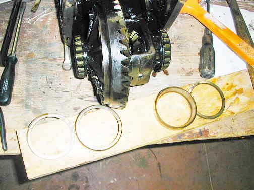
Of course normally this is in the rearend housing and runs in lube. My plan is to run this whole assembly out in the open and I'll accomplish that by replacing the tapered roller bearings with sealed ball bearings and supports for those bearings attached to the frame...
 .In the picture to the left you can see that the
tapered bearings have been removed along with the ring gear. I've bought sealed metric ball bearings (not in the
picture) that are the same size as the tapered roller bearings and they will be placed on the two bearing surfaces
where the roller bearings were, just inside of the short output shafts. I'll probably use the back caps that held
the bearings and this whole assembly in the rearend housing. I'll machine new front cap like pieces that the front
sides of the bearings will slide into (similar to the stock rearend housing) and these will also provide a place
to mount this whole assembly solid to the frame.
.In the picture to the left you can see that the
tapered bearings have been removed along with the ring gear. I've bought sealed metric ball bearings (not in the
picture) that are the same size as the tapered roller bearings and they will be placed on the two bearing surfaces
where the roller bearings were, just inside of the short output shafts. I'll probably use the back caps that held
the bearings and this whole assembly in the rearend housing. I'll machine new front cap like pieces that the front
sides of the bearings will slide into (similar to the stock rearend housing) and these will also provide a place
to mount this whole assembly solid to the frame.
I'll take a rear motorcycle sprocket blank with the number of teeth I want (probably 36 to begin with) and machine the center out so that it will mount on the carrier near where the ring gear was. I will also mount an adapter to the side of the stock ring gear mounting location that will have a disc brake rotor mounted to it. The drive sprocket will drive the sprocket mounted on the carrier assembly with a normal chain.
Since I'm getting rid of the axial (side loads) to the carrier bearings by using a straight chain drive and not the ring and pinion gear set I should be fine replacing the tapered roller bearings with the sealed ball bearings. I've talked to an engineer at one of the bearing manufactures about this and he agrees. The ball bearings will also provide less friction than the roller bearings, so this will free up some HP.
The output shafts, side gears and spider gears only move in the carrier while turning corners, so I'm thinking at B'ville I could get away with either oiling these by hand between runs or using grease on them. When they do turn they don't turn very fast as they are only there to let the outside wheel turn faster than the inside wheel in a turn.
My other alternative and one I might take is to devise a way to lock the rear as I can't find a spool or mini-spool for this rearend. I've thought I could machine up spider gears that only have a couple teeth on them so they could be assembled along with the side gears in the carrier. Since they would only have enough teeth for assembly they couldn't turn and would lock the rear. Then the only movements possible would be for the whole carrier assembly to rotate carrying the output shafts with them and that would be handled by the new ball bearings. I could also weld up the spider gears, but that wouldn't allow me to go back to an "open" rear if I wanted and also it would make disassembly of the rear very hard if not impossible.
I'm interested in input on this.
..
...............................................................Next Page