--- The Stude's 2013 Changes Page 19 --- --- Radiator In-A-Box -- Part VII --- |
With the tank now insulated on the engine side it was time to add some heat shields with air gaps behind them. I use something like this at home. We heat with a wood stove and even though it is the right distance from one wall I have a heat shield just off the wall with an air gap behind it and the wall is never even warm.
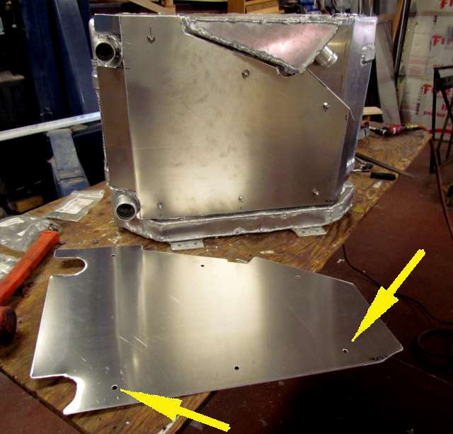
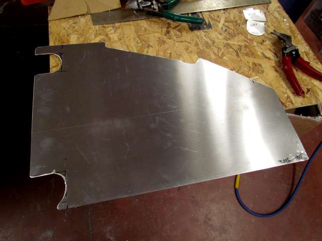
At this point I switched to .040 5052 aluminum as there was no strength needed. I use my previous pattern and modified it slightly.
.
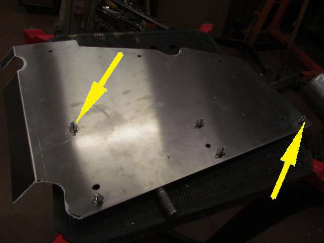
I removed the shield over the FyreWrap and drilled six 1/4 inch holes in it and put six stainless steel 1 inch bolts through from the back side and secured them with ss nuts and flat washers (not on above).
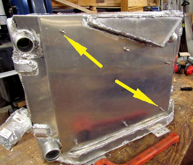
Then I drilled the .040 heat shield in the same 6 locations. I actually drilled these first with a 1/8th inch drill and transfered those holes to the .090 panel over the FyreWrap and then drilled the holes out to 1/4. With the holes in the heat shield I added another flat washer to the outside of the nuts and slid the shield above on and added another layer of ss nuts/washers. The 2 washers and nut behind this shield spaced it out from the other panel and created an air gap.
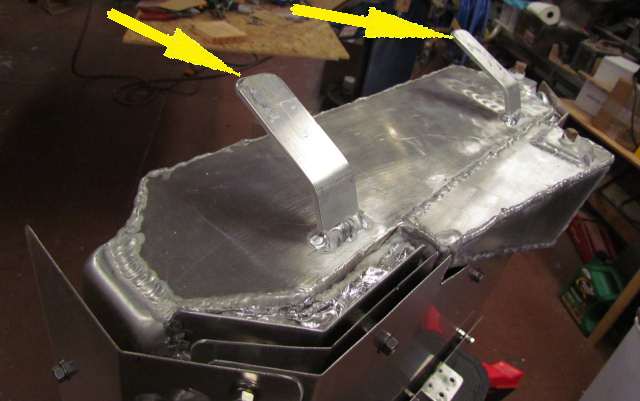
The top right arrow points to the panel holding the FyreWrap on and the other arrows point to the heat shield that was just made and the air gap that was created behind it.
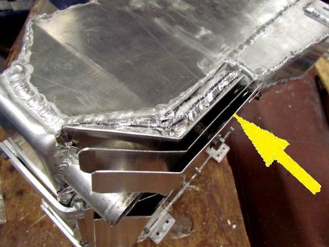
Above you can see the FyreWrap, the panel that holds it in position and the outer heat shield at the top of the box.
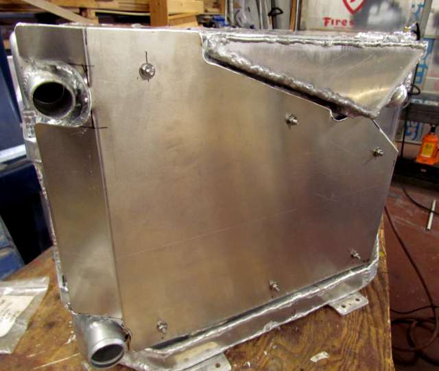
Next one more hear shield was made with the 6 holes in the same location.
It was mounted at the end of the 1 inch SS bolts.
The second heat shield might be overkill, but there was room and we want to make the rad-in-a-box as effecient as possible.
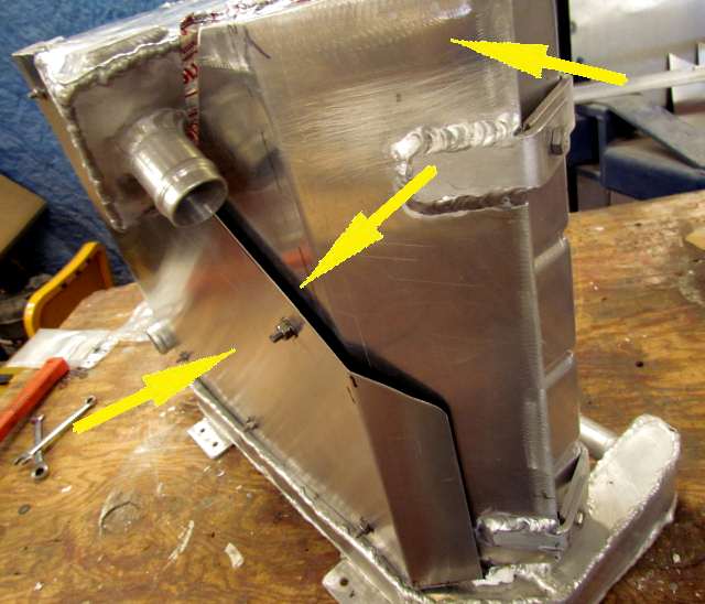
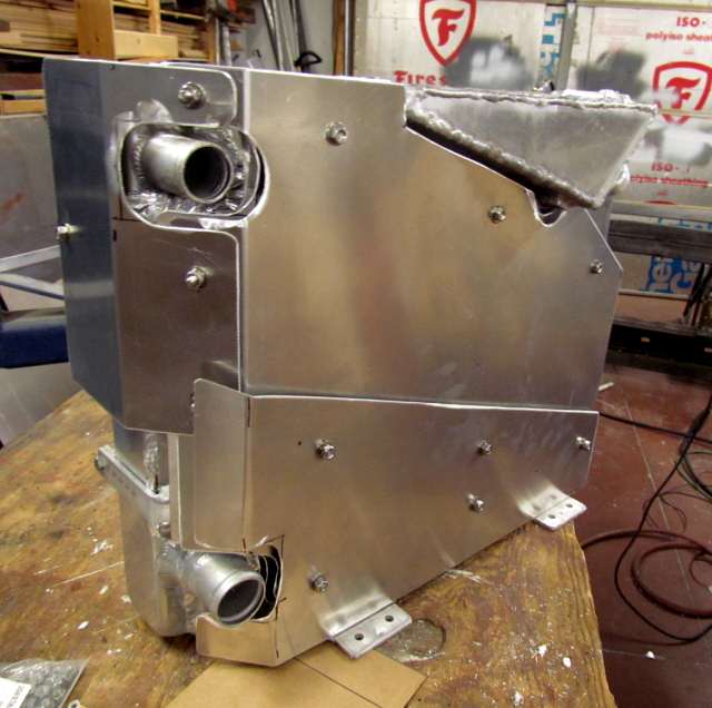
These shields did not cover the water passage around the bottom of the box where water enters the box. The area below them above.
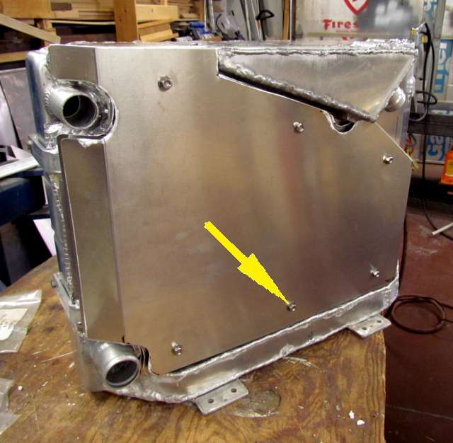
To cover that area the last shield was taken off and 5 bolts added to it from the backside and with nuts/washers on the front side.
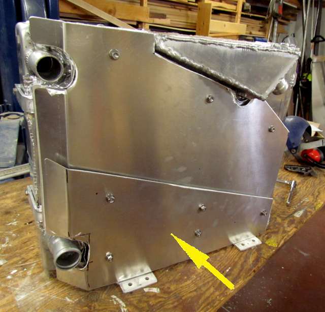
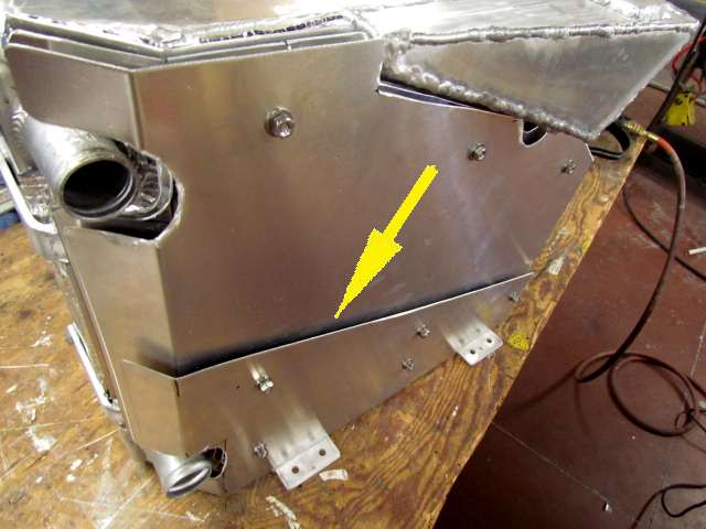
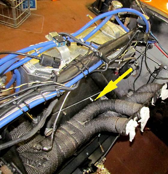
It was remounted and the smaller shield that the arrow is pointing at was cut out and mounted using the bolts from the previous panel.
It creates an air gap in front of the water passage and some of the previous panel. There are two header tubes down in this area and this will help with the heat from them as they are the closest ones to the box.
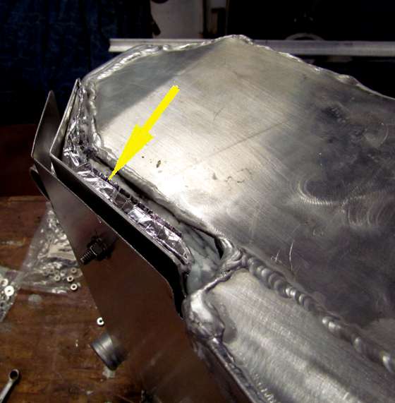
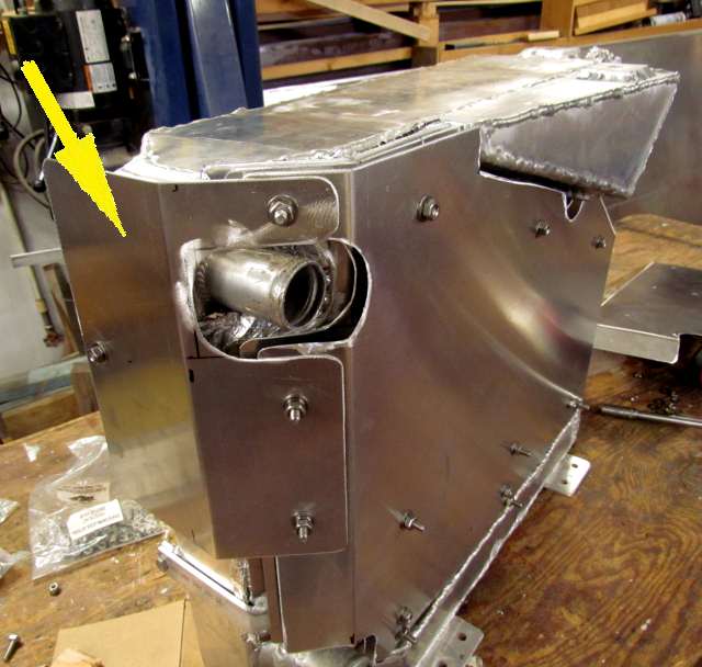
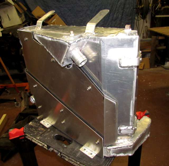
Finally one more shield was fabricated for the one end of the box as one of the wastegates on this side is a couple inches from it.
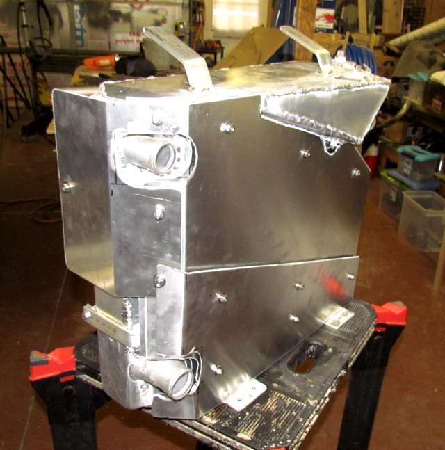
All of the shields in place.
Two mount tabs were welded to the top of the tank and ....
.... they will be tied to the down-tube in the engine compartment with other brackets. They weren't drilled as I then shipped the rad-in-a-box back to Hooley in OK and he could trim them to length and drill them and bend them if necessary.
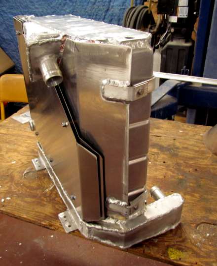
The finished rad-in-a-box. I'm happy with it if it works and it took more time to make than I anticipated as there are lots of individual pieces.
Update: The following 2 pictures were taken after 2013 SpeedWeek with the car at my house (in Utah). Hooley had taken the motor back to OK to check it out after the very high oil temp reading on the last run.
The rad-in-a-box worked very well and the only problem arose when we (I) didn't check the coolant temps after the runs and relied on the manual temp gauge in the dash being accurate. We found out after the oil heat deal that the gauge was broke and stuck at about 145 and not reading higher. So after the two runs on Tuesday and the 4 runs on Wed. in less than 4 hours instead of the main water tank being down around 145 it had actually climbed to about 190 before the last run and the coolant temp climbed to 235 by the end of the 5 miles.
Our plan had been to empty about 15-20 gallons out of the main 30 gallon tank between runs into 5 gallon buckets to cool and replace that water with water from the ice water intercooler tank and replenish that water with new water and ice. We didn't do that after seeing the 140-150 readings on the temp gauge. We will when we take the car back and will also keep track of the coolant temp as we are data logging it.
The rad-in-a-box would of worked great if we just would of kept the main tank cool and we are very happy with the results. So on to the pictures of the rad-in-a-box in the car after the event.
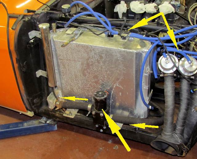
The middle bottom arrow above points to the Meziere pump that pumps water from the 30 gallon tank in the car using the hose on the right to the bottom inlet on the rad-in-a-box through the hose on the left.
The top left arrow points to the 4 port solenoid that is part of the TurboSmart boost controller system. Hoses go from it to the twin wastegates, top right arrow.
A view from the missing engine side. The pipes are close to buy not touching the outermost heat shield. A note about the engine. Hooley tore it down and found no bearing damage and we are planning on taking the car back for 2013 World finals with him driving in AA/BFCC.