--- The Stude's 2013 Changes Page 13 --- --- Radiator In-A-Box -- Part I --- |
In the past we have run a water tank in the Stude for cooling. The first year the tank was about 16 gallons, but it was replaced with one that is around 30 gallons. Cooling water was pumped from the tank to the engine with a Meziere external pump. As long as we turned the water on we had no heating problems. That was with a 400 cu. in. SBC with a roots blower. Now the engine was being changed to a 572 BBC with twin turbos and hopefully eventually much more HP. We felt that what had worked in the past might not continue to work.
Sparky, Bill Smith, had been running what he called a rad-in-a-box where an aluminum radiator was basically in a box that water was circulated through from another water tank. This resulted in a water to water heat exchanger. It has some major benefits. One is that you can preheat the motor on just the water in the radiator and not pump water past the radiator from the main water tank thus keeping its temperature lower until you start the run and turn the external pump on from the main tank to the tank with the radiator in it. Another benefit is that you can run a pressure cap on the radiator and have more water pressure in the block that can help to eliminate steam pockets in the heads. With our main tank in the driver's compartment we didn't want to run pressure in the system before for obvious saftety reasons.
Here is what Sparky has used...
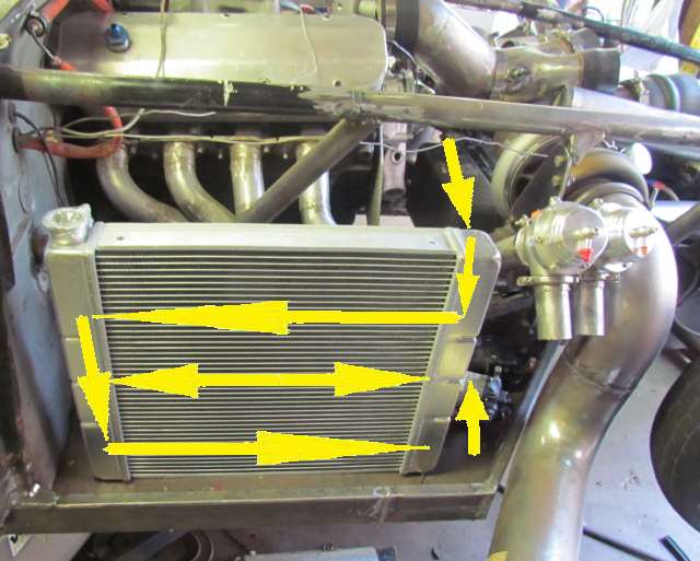
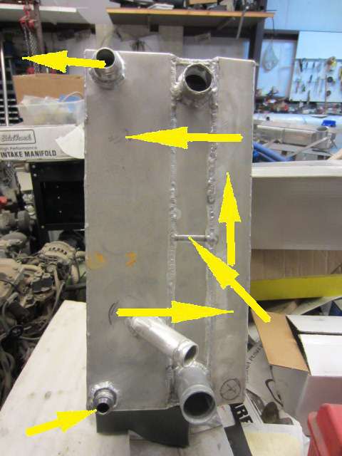
The radiator is a 2 pass radiator that is divided in half where the angled arrow is on the right. The radiator has a 3 sided box welded to it on each side. You can see the inlet and outlet for the radiator. Water enters the top and flows down towards the divider in the middle on the side tank and across the radiator to the tank on the opposite side. There it flows down the tank and then back across the radiator (2nd pass) to the outlet on the same side that the inlet is on at the bottom.
The cooling water takes an opposite path. It enters bottom left and flows up to a divider in the left side tank and then across through the radiator to the tank on the opposite side. Up that tank and back across through the radiator and out the outlet, top left.
The other outlet I think is the one Sparky uses to pump the tank somewhat dry so that even less water is pre-heated during motor warm-up and before the run starts and the electric pump is turned on.
The arrows point to where there is a divider in the tank on the side with the inlet and outlet. The divider forces the water through the radiator to the tank on the other side.
We did something very similar, but don't have the option of pumping the tank half empty.
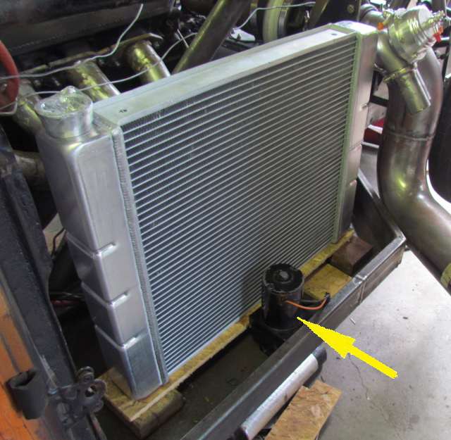
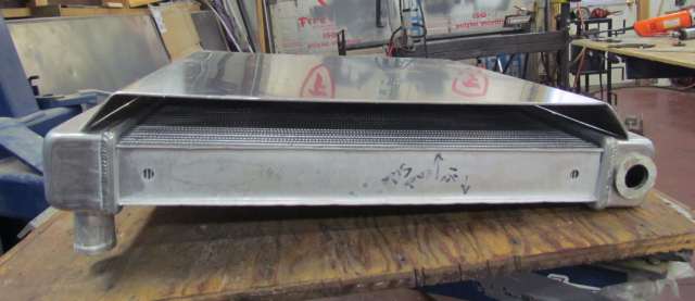
Hooley ordered in a radiator that was a 2 pass with the inlet/outlet on the right side in the picture above as that would put them at the front of the engine. This is a 'Ford' style tank.
The arrows again show the water flow with the 2 pass radiator. The double arrow divides the radiator into the top half, first pass and the bottom half the second pass.
With the extended front-end on the Stude and and headers going to the turbos vs. the zoomies that exited out the sides of the fenders room became available in the fender areas. Hooley put in an outer frame member and added a floor to the space. We decide to try and put the rad-in-a-box on the passenger side and the ice water tank for the intercoolers on the driver's side of the car. Being next to the headers this is going to require some insulation and heat shields, but if it works will give us some weight forward in the car which will help with the Center of Pressure/Center of gravity deal and will cut down on some long plumbing lines.
Above you can see how the inlet/outlet for the radiator is in a good position for connection to the water pump and the return from the block.
The Meziere pump will be mounted outboard of the radiator next to the fender.
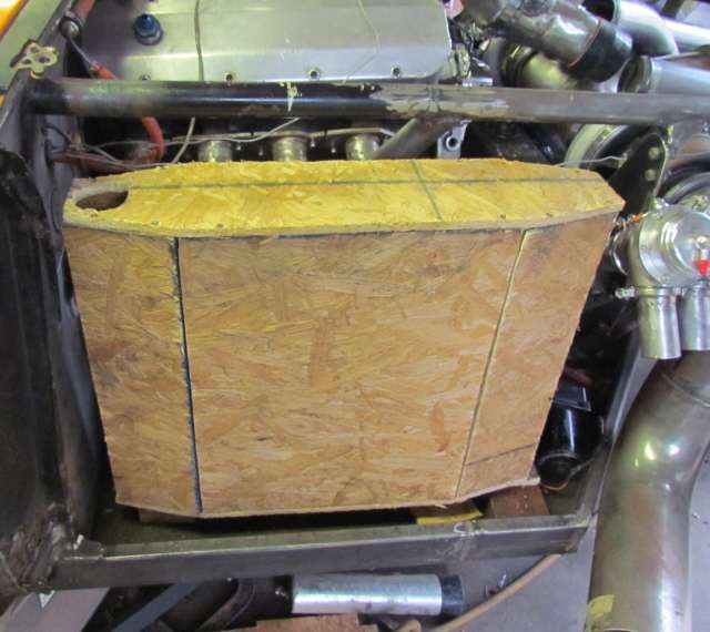
While I was at Hooley's I made a box to take home that fits the area and that I can use to make sure what I build will fit back into the car hopefully.
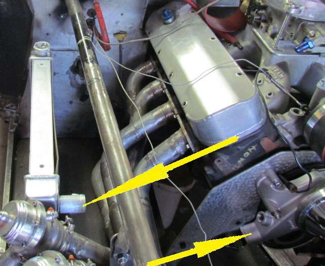
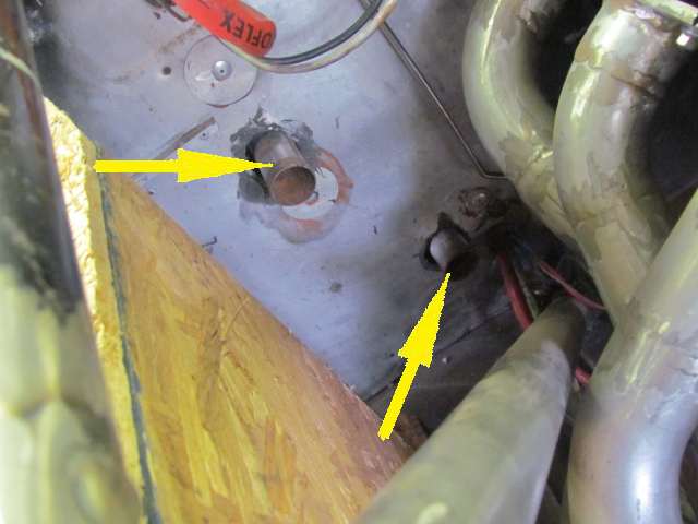
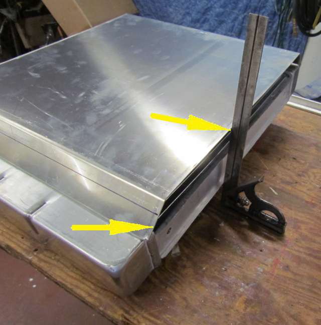
Above the side of the box is to the left and the picture is taken towards the firewall with the engine to the right. The bottom arrow points to the outlet from the 30 gallon tank in the driver's compartment. A line will run from it forward around the front of the box to the pump on the fender side of the box in the previous picture.
The water will then flow from the pump around the rear of the box and enter on the inside and go up and through the radiator twice and out the top inside of the box and return to the inlet to the 30 gallon tank, top arrow.
The fitment of the tank made it hard to get to a pump on the engine side of the tank and into the tank there thus the route around the box for the inlet to it.
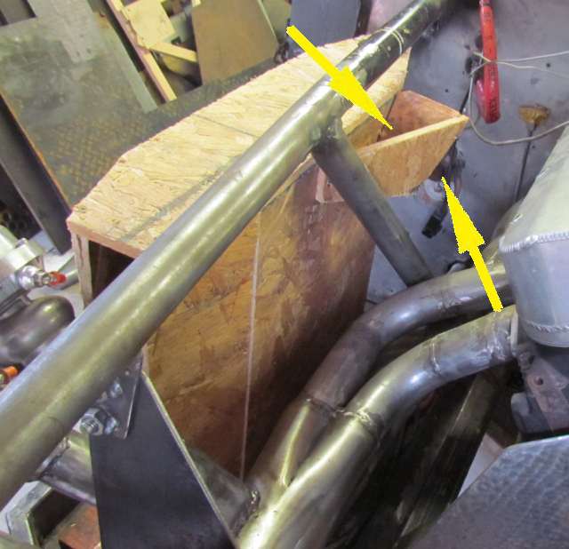
The bottom arrow points to the return to the tank and the top points to a side extension off the box where a return 1 1/2 inch spigot will be located for a hose that will go to the tank inlet.
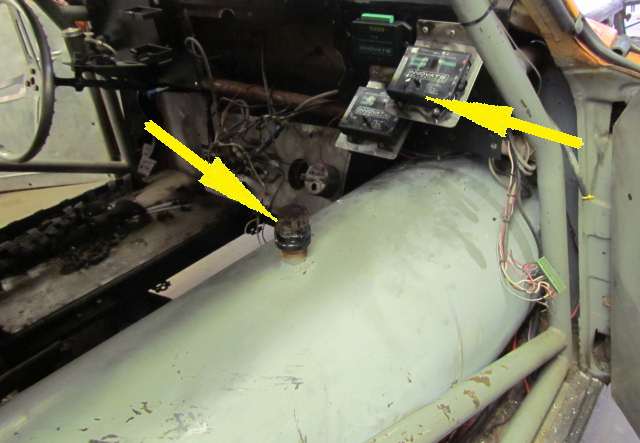
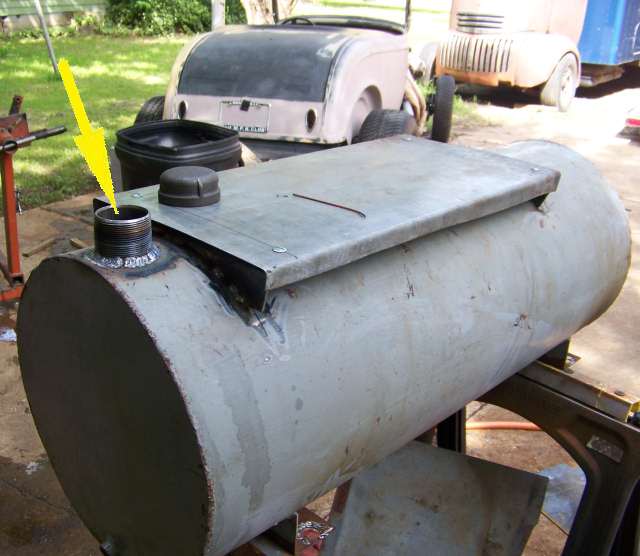
Above is the main water tank which will supply the water to the rad-in-a-box. The right arrow points to the additional Innovate Data Logging devices that have been added to the can and that can data log 16 different channels.
The other arrow points to the old fill for the tank. Hooley....
... removed the old fill and plugged it and added the brackets above and...
... moved the fill to the end and put a platform on the brackets so that he...
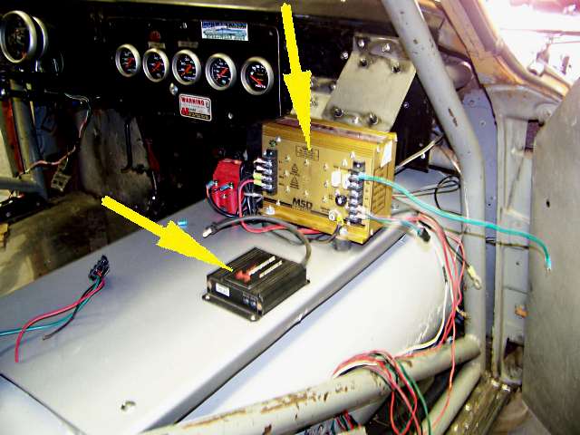
...could use the area to mount other items like the MSD box and the Snow Performance water injection controller (bottom arrow).
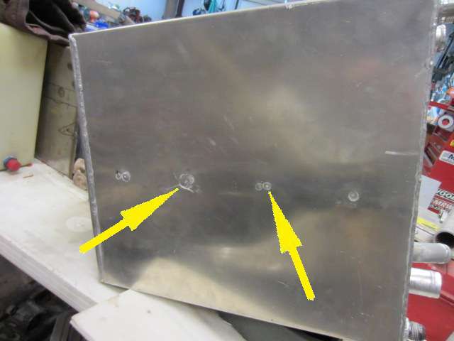
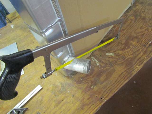
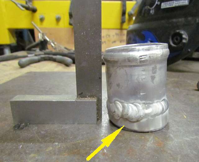
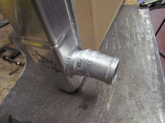
Arriving back in Utah I went to work on building the rad-in-a-box. The first item was to change how the output from the radiator was orientated. It came out at an angle and we needed it to be straighter to get it headed towards the water pump inlet. I cut it off with a hack saw and....
.... then welded a short extension that was angled to the piece cut off so as to keep it long enough for the hose and a hose clamp.
Then it was welded back onto the radiator facing in a better direction.
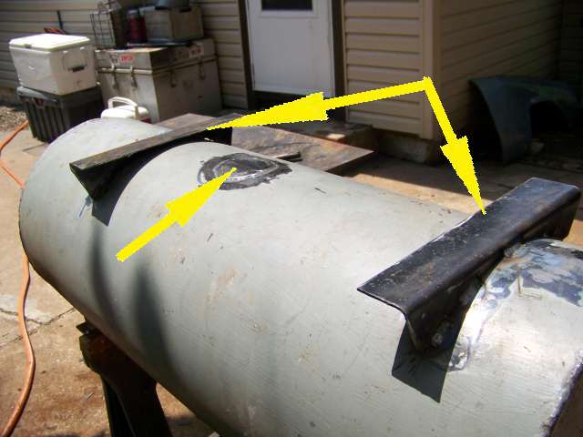
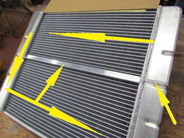
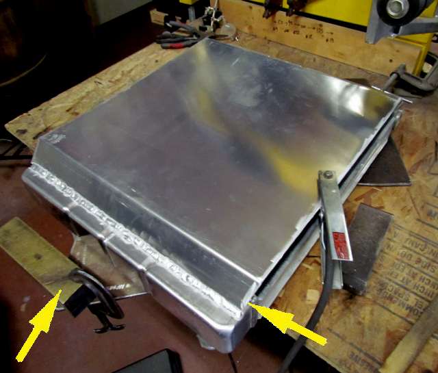
The right arrow points to a weld seam where a piece was placed in the side tank by the manufacture to force the water over to the other side tank for the first pass of the cooling water. There it flows down the other side and back across the radiator, second pass, to the tank on the inlet/outlet side and out the outlet and to the engine's water pump.
The middle vertical arrow points to a piece of angle I had cut that is going to be part of a diversion baffle for the water that will also make two passes through the tank.
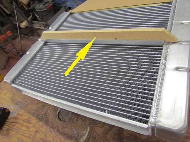
The particle board piece, arrow, that is on the angle represents the baffle that will be made later in the build. It also gave me the angles that I wanted to bend the box sides to in order to move water and to also be welded off to the sides of the radiators side tanks.
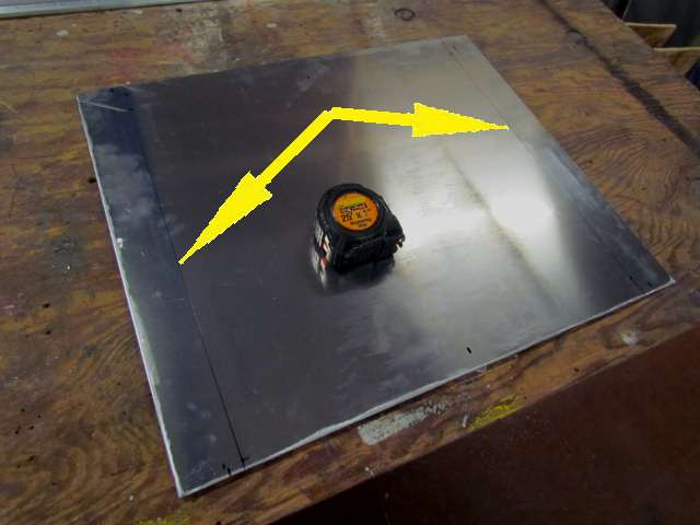
Above is the piece that will be bent and welded to the side of the radiator where the water will flow from bottom to top after it makes the first pass through the radiator from the other side (picture before this one). The lines on both sides were....
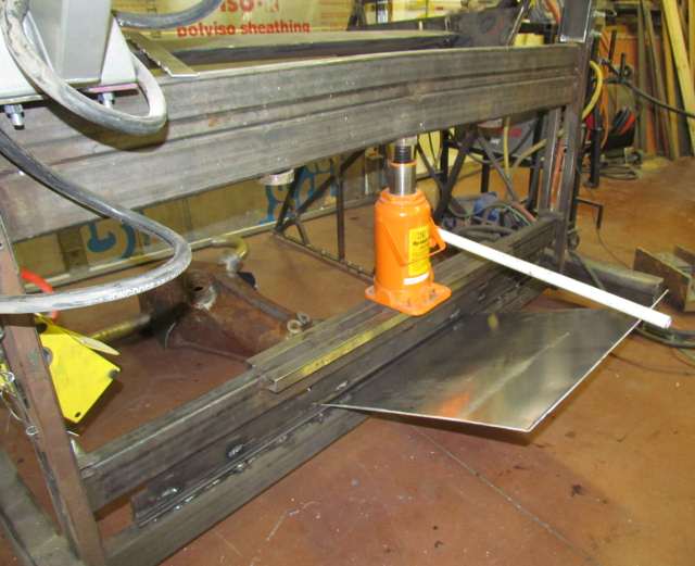
... where I bent the panel in my press brake that I had made.
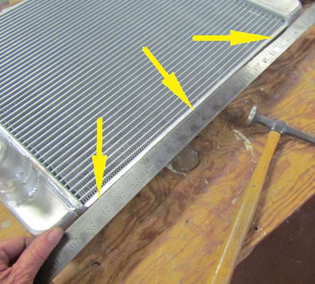
I noticed that the radiator had a bow in it at the top and bottom. Notice that with the straight edge on the bottom there are gaps in both sides. I was able to straighten these out by tapping on them with the body hammer until they laid along the straight edge.
This was done on both sides of the top and bottom and needed to be done so that later when the end caps were welded on water didn't flow from one side to the other in the gaps vs. through the radiator. I also used the square to make sure both sides were square with each other for the same reason.
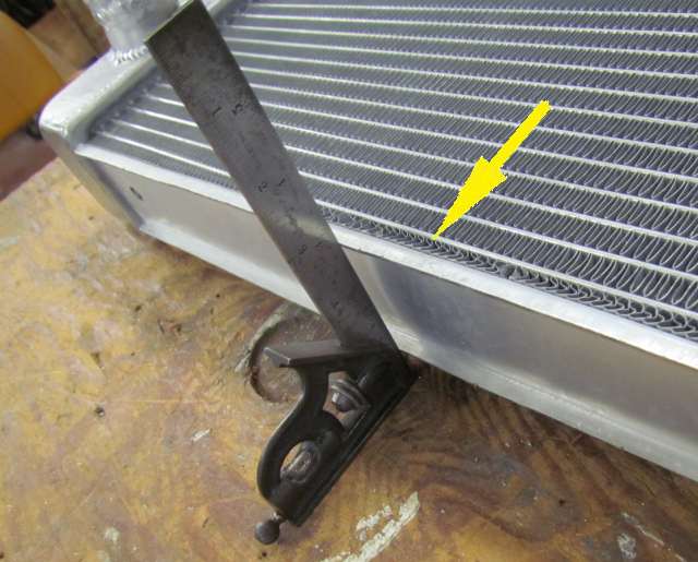
This compressed the cooling fins some, arrow, but the efficiency of this rad-in-a-box is much higher being water to water vs. air to water so I felt this didn't compromise the cooling.
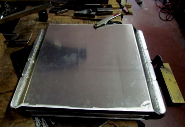
This also had to be done so that the new box sides were also square with the bottom of the radiator as shown above. The left arrow points to an area of the side that was later tapered down so that the end cap flowed down to the radiator side tank for welding there.
The side pieces were bent so that they were 1 1/2 inches high above the radiator side tanks.
Next the side was welded to the side tanks. You can also see how the side was tapered to the side tank, right arrow. The left arrow points to a temporary support for me to rest on while welding.
One side finished.....kind of.