Return to Tech Info Page..........................Return to Sumner's Home Page
..................................................................Next Page of 700R4 info.
.......................................-- More
Tech Info on the 700R4 --
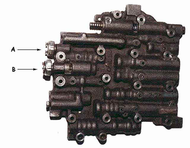
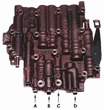 The following information is from Tony of RRT. (thanks Tony) -- In
the photos of the 700r4 valve bodies with and without switches: "A" is where the switch for convertor
lock up in 4th gear needs to be installed. I recommend removal of the other switches (if any) and 1/8th inch pipe
plugs installed.
The following information is from Tony of RRT. (thanks Tony) -- In
the photos of the 700r4 valve bodies with and without switches: "A" is where the switch for convertor
lock up in 4th gear needs to be installed. I recommend removal of the other switches (if any) and 1/8th inch pipe
plugs installed.
In the photo with out switches : "C" is a valve that should be blocked
in place. This requires removal of the valve body from the trans. Many DIY ppl will not do this since gasket tear
is possible. It's easier to block the valve during the rebuild process of the trans.
A blocking pin about 1/8th diameter (welding rod), .890 long works well. Leave
the spring in place. This blocks the "line bias" valve and improves shift firmness above 1/2 throttle.
Transmission
Identification for 700R4 -- Tony's 700R4 pages
More Information from Tony: 700 trans
have NO modulator, never did.
lock up Solenoids can have 1 or 2 wires. 1 wire is self grounding, 2 wire is not. 2 wire is later model (85 up,
i think) and is what most ppl see now a daze.
Power is routed thru brake lite switch first, that way the brake pedal over rides every thing.
factory wiring harnesses in 700s have been many and varied! they became consistent in about 86 or 87 with some
variations.
Your kit provides for l/up over ride as I remember. That is why they route the ground back out the case connector
"D" which is the same for the factory setup for many years.
I do not believe your kit has a temp sensor in the harness like the factory does. Temp sensor over rides lock up
in cold climates. I am not familiar with the lock up kits since I do not use them.
12 volts to "A" and ground to "D" should provide lock up on most late 700's .
Speedo gears are the same from 1981 till the 700 went to electronic speedo
which was not all models in the same year of start of electronic speedos.
The 700 pump is virtually the same from 1982 thru 1992 except for vane count,
slider springs (early 1 spring,late 85 & up 2 springs), and pump bushing bore with a retaining edge. In later
pumps the bushing must be installed from the inside of the pump because GM left a machined lip to help prevent
the bushing from walking out the front. On early pumps you file some notches on the inside edge of the bushing
bore and "stake" the bushing in place while using red lock tight. Always use the 4L60E bushing as it
has a Teflon type
coating.
Installing dual springs for the slider is simple and cheap. Early pumps have 7 vanes, later pumps have 10 vanes,
with 1996( I think) and newer have 13 vanes. A 7 vane pump has plenty of volume to operate the trans. Industry
trans ppl have told me the vane count increase was to quiet the operation of the pump, not really to increase pump
volume. That statement makes little sense to me, so take it any way you wish.
The second valve body on 700's is actually an accumulator for forward clutch pack engagement. This softens the
apply feel of the trans into drive. They also installed a check ball into the case to soften reverse clutch pack
engagement. I remove the reverse ball and either limit the accumulator pistons movement in the second valve body
or install a stiffer spring in place of the stock spring.
Depending on price a later trans is preferred, but early ones can work just as well.
A 700 from a 4.3 V6 usually is cheaper to buy and they have the same internal hard parts, only fewer friction plate
count, which is easily corrected........
The seal popping is a reason the drain hole must be enlarged on the early pump bodies.....ALSO enlarge the
hole in the stator/pump cover body too! Many ppl over look this hole for the drain back.
Keith, also make sure your shop instals a 4L60E bushing, they are coated and a late type seal has 2 lip seals (oil
& dust). Make sure they file notches and stake the bushing with loctite! Loctite the seal and use the seal
retaining collar to.
I had a staked bushing move last year on a truck that the guy was towing sand buggies in 3rd gear , not locked
up. The bushing will move out and touch the seal , you then have a serious leak! The customer got the trans very
hot! I changed lock up to 3rd gear foe him instead of 4th gear only.
The lube hole at the lock up valve should be at least .110 for better lube in lock up mode for the rear planet.
What ever the hole size is , opening it up 30% will double the oil flow! A fluid engineer told me this.
A competent shop will know the mods necessary to help this trans, if not I can help .....I hope , LOL
For Improper Shift Points ==== verify full TV pull at the trans. Or a guage on the pump pressure port will
show line rise as the cable is pulled even at idle. Your trans expert will have the tools to test this.
If the line rise is good, then put softer springs in the govenor. This should raise the shift points. If the shift
points are raised, but not enough, grind the weights off or install a vette govenor and try that. The gov springs
can be cut off a little too. I build 8-10 various transmissions a week and do this often
If that does not work, you need a stiffer spring in the 2-3 shift valve. Start with a spring 1 pound stiffer.......it
does not take much to change the shift point.
Also check the TV "up" and "down" valves in the valve body. if one or both is stuck that will
cause it too.
Sometimes a bigger boost valve and spring will throw the calibrations of the valve body way off (if these were
installed)
Tony
And more from Tony.....============== there are several things to do for 2-3 shift improvement. First block
the line bias valve in place. This valve blows off main line pressure above 1/2 throttle. A steel pin 1/8 inch
in diameter about .890 long fits most of them and fits inside the OEM spring.
The shiming of the 2nd gear servo is important. That servo is also the accumulator for 3rd gear. THe bigger TransGo
kits come with a gold ring, about an 1/8 inch thick to shim the 2nd servo area with. This is a good shim to use
to shorten servo movement and shifts on the 700.
there is a new band , about 3/8 inch wider than OEM style units. You must have the drum fairly surface flat, check
it with a straight edge. A lathe may be needed to trim the drum up a bit to flatten it out. The drum will chatter
in the lathe while machining unless you use a disc brake rotor strap to calm chatter effect. A rubber bungy strap
works too.
Always check band clearance, the output shaft should turn both ways. One direction is harder to turn than the others.
The hard turning direction is the band grabing the drum. If you need to use channel lock pliers to turn the shaft
that direction, yet it turns fairly easily with the pliers the clearance is OK.
The aluminum second gear servo has a large spring under the steel cover that the servo pin goes thru. Removing
this spring and cover, shimming up the pin as needed removes the 2-3 shift accumilation from the system. Use a
093 vette servo, aftermaket # is 93-1.
The gear spacing on a 700 is something I have never liked. 3.06 first, 1.83 second gear. Thats a big jump in gear
ratio. That may not help drag times. We drag raced a shoe box nova in the early 80's with a 700 trans. 5.38 gears
allowed short use of OD thru the traps.
Alto offers a 3-4 clutch kit with red frictions that works very well. Kolene steels help to reduce problems from
heat build up in the 3-4 clutch pack ( a commom problem).
Next Page of 700R4 info.