.....
I was having a hard time finding a cut-off tool holder for my Harbor Freight 12" X 36" lathe. I needed something that would mount the cut-off tool with the top of it at 1/2" in my 4-way tool post. Since the cut-off tools are 1/2 inch high about everything I found would mount the tool too far above center.
After searching the Internet I found some tool holders that I thought I could copy that would work fine.
.................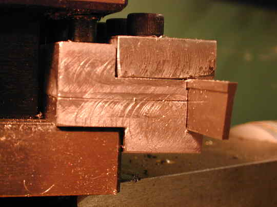
Here is the finished holder. There are two main pieces that make up the body and one piece on top that clamps the cut-off tool. The bottom could have been made out of one piece, but I didn't have one piece that was thick enough so I used two pieces and they are screwed together.
You can see the tool sets in the 4-way tool post and drops the cut-off tool down so that the top is 1/2 inch above the bottom of the 4-way tool post. I machined in a small slot for the top of the "T" shaped cutoff tool to fit into so that the cut-off tool is flat against the side of the holder.
The ledge on the top right of the holder is machined so that it is a little lower than the top of the cut-off tool. This then allows the piece on the top to firmly clamp the cut-off tool.
.................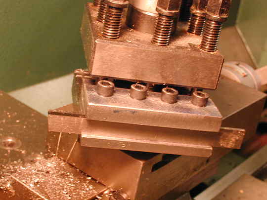
Here it is mounted in the 4-way tool post. The four allen screws clamp the top
and are threaded into the main body. The two piece body I was stuck making due to a lack of the right thickness
material is held together with screws (see picture below) and also from the clamping force of the 4 way tool post.
.................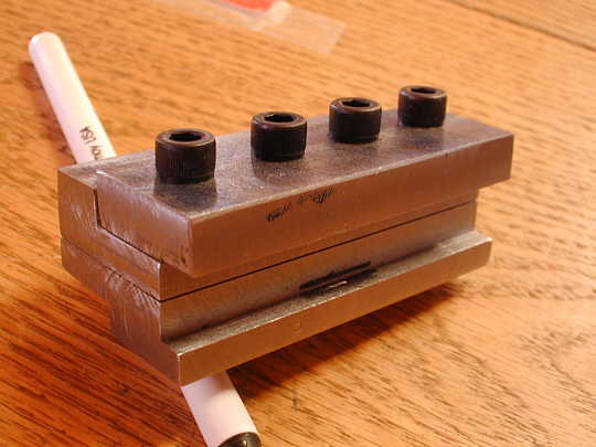
A picture before the small cut-out was machined in for the "T" top of the cut-off tool. I made the holder to this stage and then had to wait to get the cut-off tool to see how much I had to machine out for the "T" top.
.................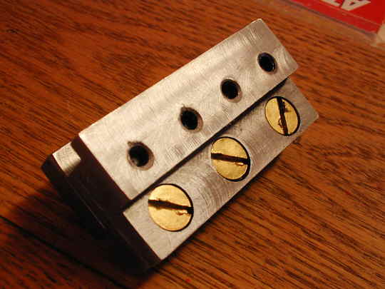
A view of the bottom showing the screws that hold the two pieces together and also showing the tapped holes for the allen screws that bolt the clamping piece to the main body.
.................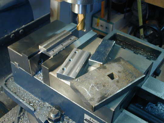
A picture of the plate that I started with in the foreground to the right. I cut it to rough size with my chop saw and then machined all the surfaces with the mill. At this point I was working on the two pieces that make up the main body and you can see the smaller, still rough, piece that will be the clamping piece on the top of the finished tool.
Hope this is enough pictures to see what you have to do to make a tool like this. This was my second milling project.
...............................................Return to Metal Working Index
.................