.....
I have an Enco Model 105-1145 21" Swing Geared-Head Mill/Drill. I wanted an attachment to fix a Dial Test Indicator to the quill where I wouldn't have to remove the cutting tool from the quill. As far as I know Harbor Freight and Grizzly sell the same mill/drill with their names on it. This is a Chinese product. Enco and others sell an attachment for this, but they are around $40 to $50 and seem to be sized for the Bridgeport mills that have a larger quill. After looking at pictures of these I though I could build one.
.................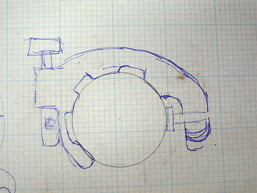
I began by making a sketch of what I wanted. The inside circle represents the diameter of my quill. A bolt will come in from the right to clamp the "C" shaped attachment to the quill and on the other side there is place to attach the universal arm that will hold the test dial indicator. I had the test dial indicator and was going to use the adjustable arm off of a magnetic base indicator holder I had.
.................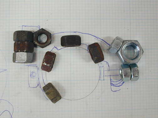
I didn't have a piece of aluminum or steel to use as a starting place for the
project, but I did have a piece of 2 inch pipe and some bolts and nuts. Not the prettiest solution, but cheap and
available. I laid out the nuts on my sketch in the position they would be welded to the pipe.
.................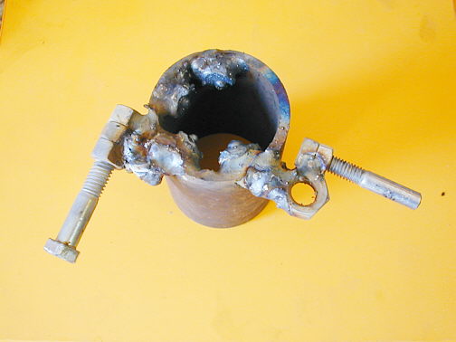
Next I took my mig welder and welded everything together. Not pretty, but it
will work. The nuts are on the inside of the pipe to reduce the diameter down to a size that will work on the quill.
Next I took the grinder and die grinder and cleaned up this mess the best I could, but left everything oversize
so I could take it to the final clearances on the mill.
.................
I put the pipe on end in the mill vise with a V-block and used an edge finder to locate and center the pipe under the center of the quill. Next using a boring bar I cut the center out to the diameter of the mill quill. In the process I cut into the nuts that were welded to the inside of the pipe and that gave me a circular surface to face up with the quill diameter.
After boring the center to the right diameter I used an end mill to slot the pipe where the set-bolt would come in from the right. Then I used the end mill to face the surface of the pipe.
I also drilled the hole in the 3 nuts to the left for the arm for the test indicator holder.
.................
After I finished the one side of the holder I put the pipe in the lathe and cut most of the pipe off. Actually I cut almost through in the lathe and finished with a hacksaw in my vise.
Then I put the holder back in the mill vise and cleaned up the inside bottom of the welded in nuts and the other face of the pipe.
.................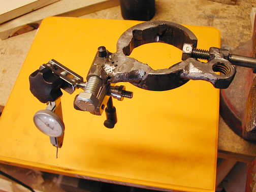
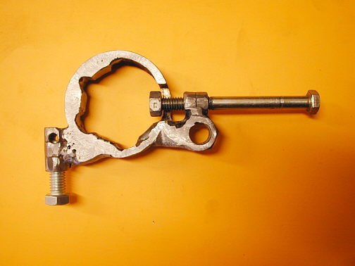
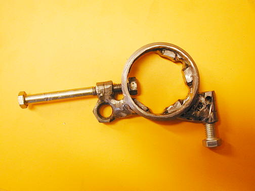
Here is the finished holder with the test indicator attached.
.................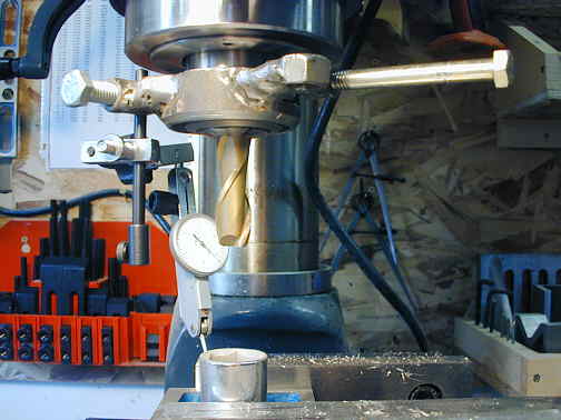
And a picture mounted to the quill of the mill with an end mill still in the quill.
This is one of the first projects I made using my mill and although not real pretty it seems to work fine.
...............................................Return to Metal Working Index
.................