................................................Return to Harv's Index Page
.....................Previous Page..................................................................Next Page.
................--- Transmission Adapter & Cockpit ---
..........................![]()
This is the start of adapting a Mazda 2200 transmission to a 1.9 Saturn engine. I cut the front of a Saturn stick transmission off with a Saws All and had a friend true it up in his Bridgeport.
Thanks Stu Cohen.
.......................![]()
The transmission shaft was about 4" away from the flywheel at this point.
...................... ![]()
Next I cut the Mazda transmission flange off (laying on the table). To the scrape pile with it!
......................![]()
The next step was to make a plate to weld to the Saturn transmission base. I used a piece of 1/4" 6016 T6 plate that was cut on the (at least 60 year old) wood band saw.
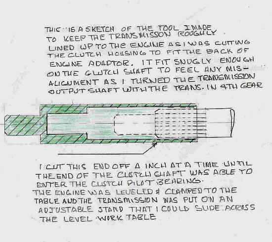
.............I made a pilot extension that slid over the transmission shaft and pilot bearing snout and duplicated the snout on the extension. A sleeve was turned to fit in place of the clutch pilot bearing for the transmission and transmission extension to fit with minimum clearance.
......................![]()
I cut the Mazda case down a little at a time and kept it roughly lined up as I progressed toward the engine using the alignment tool I made (see previous drawing). I removed the alignment tool when the shaft started to enter the locating sleeve. The housing was cut and filed until the splines where within 3/16" of the locating sleeve. The case was then welded to the original Saturn transmission flange.
Next I placed a dial indicator on the transmission input shaft and rotated the input shaft by turning the output shaft with the transmission in gear. As the indicator rotated on the shaft it was read with a mirror through the clutch arm hole in the side of the transmission. Readings were taken at four locations on the flywheel and the transmission was removed from the engine for filing on the front of the original Saturn transmission flange (about twenty times). Eventually the dial reading was within .002" on the round trip of the flywheel. I wouldn't recommend this process.
.........................![]()
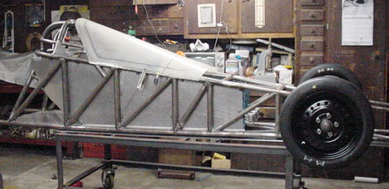
The almost finished transmission adaptation. It still needs the dowels relocated and a clutch and new custom flywheel. 10,000 RPM says they can fix me up. Also pictured is my mill!!
................
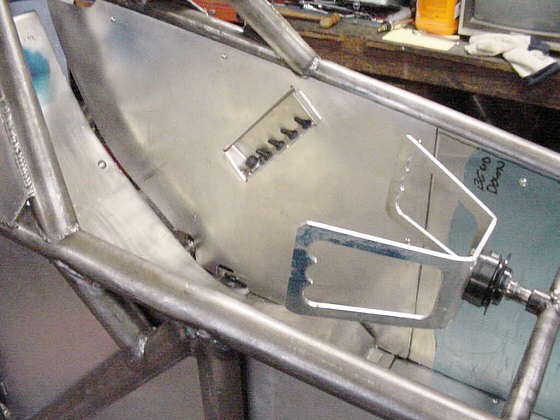
I have the cockpit lining roughed out and.........................................................................
................
......................................a small start on the electrical with some switches!
................
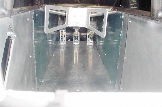
This is the beginning of the outer skin planning stage, just a start but a start, also if you look close you can see the 3/16" steel sheet resting underneath it. This will be the belly pan. It will be bolted on 1" below the lower tubing and hopefully, save counter weighting the front. This will keep the extra weight as low as possible, allow a space for brake, clutch and throttle lines, wiring and maybe coolant tank lines if I need even more weight on the front. This will be at a cost of 26 square inches of frontal area. Not much when you compare that to 290 square inches of the back tires.
.........................................................................Next Page