................................................Return to Harv's Index Page
.....................Previous Page..................................................................Next Page.
.....................--- Shift Linkage, Motor Mount ---.................--- Seat Belts and Throttle Bodies ---...........................
......................................
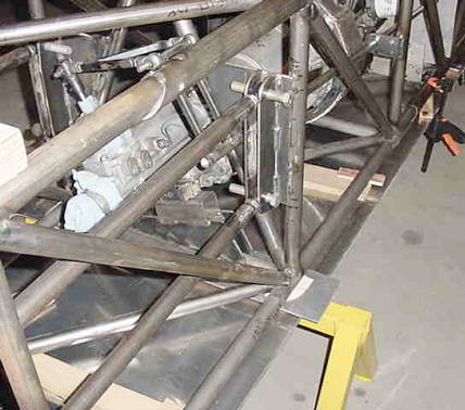
Shifting linkage went better than I thought it would. The shift pattern stayed the same so I was able to use the old knob and stick. The shift forward and back is 1" from neutral for each. The total sideways is about 10 degrees.
......................................
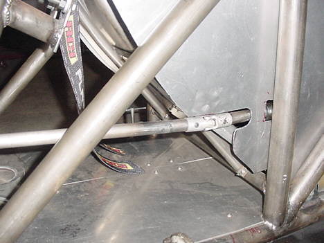
The shift rod at the fire wall will need some type of a seal. I'm thinking maybe a large fire protector sleeve for a hose. Any ideas?
.....................................
The gates in the transmission and the spring load to 1st. and second are easily felt. The shift to 5th has a little more spring load but the gate is easy to feel. Reverse is blocked out internally in the transmission. In fact the reverse gears have been removed.
.....................................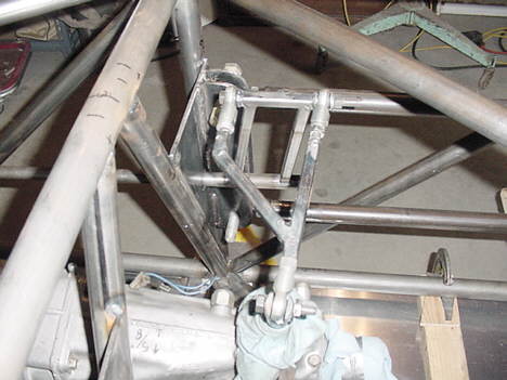
The rear cross over linkage will have a couple more 1/2" tubes added. There was a question about the oiling to the rear yoke in my mind when I removed them but I think I decided it was going to be all right. I'll run it with the driveline out and make sure! If I don't get oil out the back, I'll have to do something about it.
...........................................
The rear belly pan will be .090 aluminum. The front section was 3/16" steel. Both attach with bolts and nuts.
......................................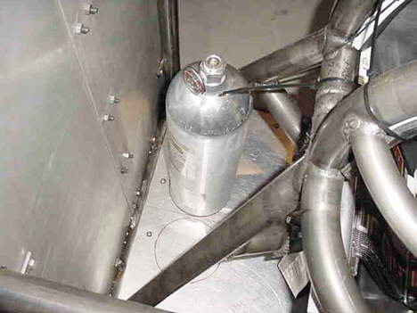
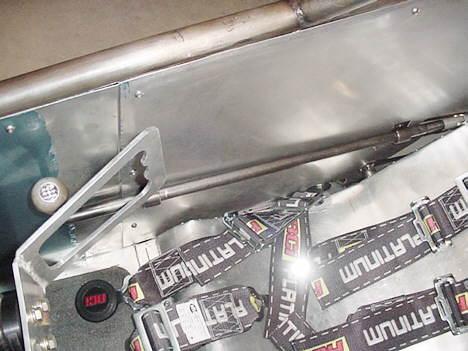
The borrowed ColdFire tank shows where tanks will be mounted. This area will also hold the outside air helmet pumper and a laptop that will be needed (I believe) to store data taken from the older TecII ECM.
......................................
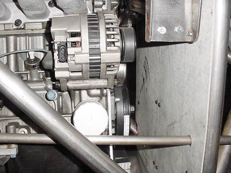
The front engine mount is a stock item that was mounted on removable rectangular tubing that also serves as a frame crossmember. The engine mount will be shimmed to take some of the weight off of the engine plate lower mounts.
..................................
This was the first cockpit fit up with the SFI 20 fire suit (second hand, as is all the personal safety equipment )and pointed out a few things that will have to be changed and where the gauges and misc. controls will be placed. .I found that I couldn't tighten the safety harness myself and the polyester webbing took more strength to pull tight than my wife could muster. I put on the arm restraints after the picture was taken and pulled all the imaginary controls with the right hand including the switches located at the left elbow area. All in all, pretty satisfying....
.......................................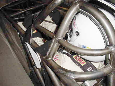
The cage fits the helmet well.
......................................
The seat, belts, shifter and steering.........
.................................................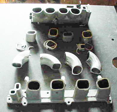
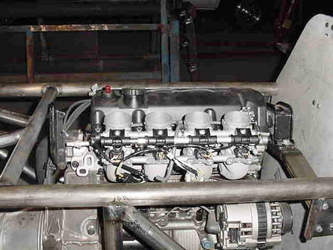
Throttle bodies: I ended out with less room for the throttle bodies than my eye ball engineering told me. It was a good thing I had tilted the engine already, because it would have never fit. I wanted to have a minimum total length of 13" for the intake track and to get it within the confines of the original body plans it had to turn the TB's to vertical. .....
................................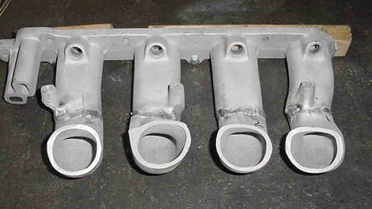
That required a 72 degree bend in the manifold. I had a spare manifold so I went crazy with the bandsaw and cut it up in pieces. Threw out the ones I didn't need (not far) and welded some up. I saved enough to use the stock injectors and rail, this will keep the injector spray on the intake valves and the price of injector replacement down. ....
.................................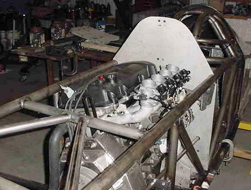
I will leave the Hayabusa injectors in just below the throttle body plates. They are the same impedance as the Saturn injectors. May be fun to play with but I'd have to get more info on the Busa vacuum system before I plugged it off. I have to have a signal for MAP to the ECM and will have that from four tubes below the throttle bodies. ....
.....................................
The molded Busa TB connectors have been ordered for the manifold and air box so the intake manifold can be finished up and the airbox fabricated. That was a shock for a guy getting most of his parts at the Pick and Pull!....
.........................................................................Next Page